# Physical environment configuration
This section outlines the steps to be performed to configure the physical environment used in this solution.
# Switching and cabling
Figure 7 describes the cabling configuration of nineteen (19) HPE ProLiant DL Gen10 Plus Servers as well as the HPE Aruba 8325-32C BF switches and Aruba VSX, that takes advantage of the ArubaOS-CX modern architecture, and delivers best in class high availability within the context of this solution.
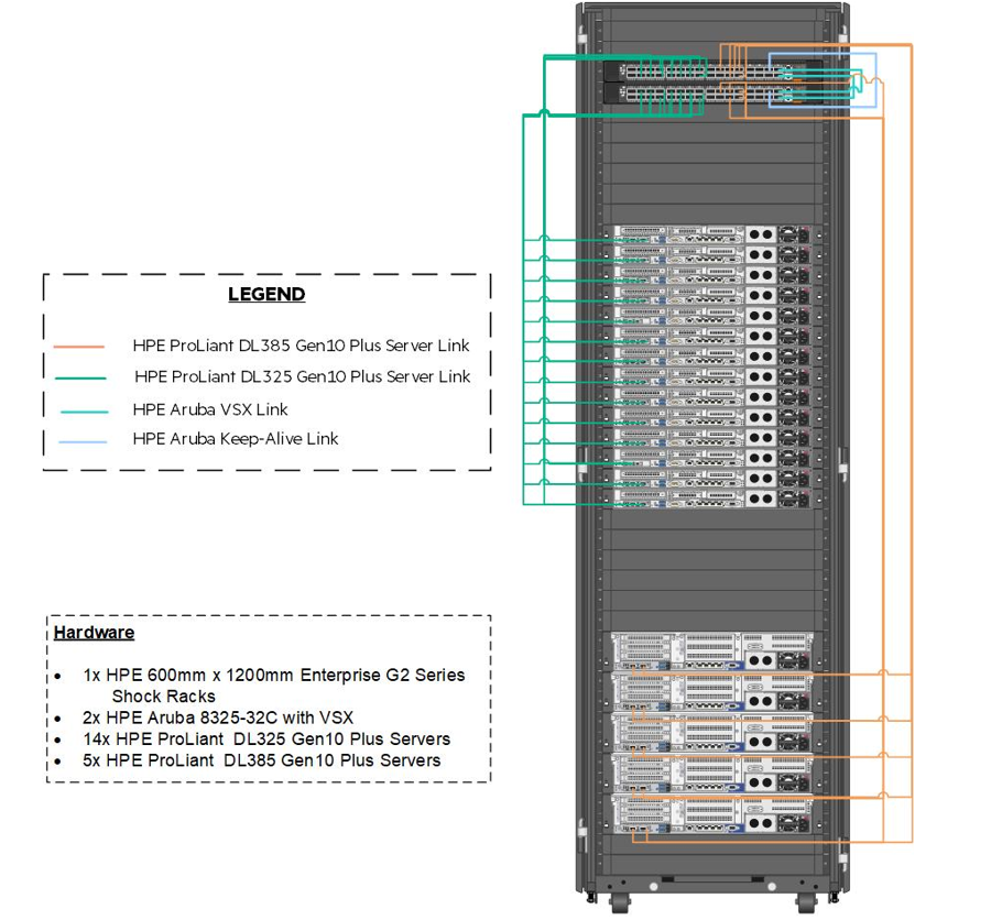
Figure 7: Cabling of the management and inter-frame communication links within the solution.
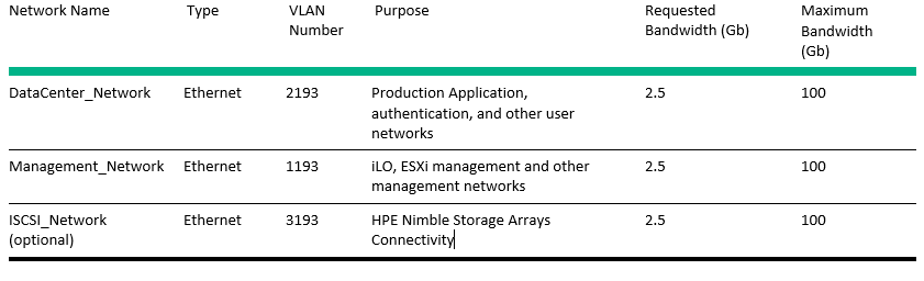
Table 5 explains the cabling of the Virtual Connect interconnect modules to the HPE Aruba 8325-32C switching.
# Table 5 Network used in this solution
# Physical cabling
Table 6 represents mapping of source ports to ports on the HPE Aruba 8325-32C switches.
Table 6: HPE Aruba port map

Hewlett Packard Enterprise recommends that the installation user logs on to the switch, post-configuration and provide a description for each of these ports.
# Network definition
There are multiple networks defined at the switch layer in this solution:
Management Network -- This network facilitates the management of hardware and software interfaced by IT.
Data Center Network -- This network carries traffic from the overlay network used by the pods to external consumers of pod deployed services.
# Configure VLAN
This section details the steps required to configure a VLAN.
- To add these networks to the switch, logon to the switch console over SSH and run the following commands.
> sys
> vlan 1193 2193
- For each of these VLANs, perform the following steps.
> interface vlan-interface ####
> name VLAN Name per table above
> description Add text that describes the purpose of the VLAN
> quit
NOTE
Hewlett Packard Enterprise strongly recommends configuring a dummy VLAN on the switches and assign unused ports to that VLAN.
- The switches should be configured with a bridge aggregation group (BAGG) for the different links to the HPE DL Server connections. To configure the BAGG and ports as described in Table 5, run the following commands.
> interface Bridge-Aggregation111
> link-aggregation mode dynamic
> description <FrameNameU30>-ICM
> quit

> interface range name <FrameNameU30>-ICM interface Bridge-Aggregation111
> quit

> interface range HundredGigE 1/1/1 to HundredGigE 1/1/2 HundredGigE 2/1/1 to HundredGigE 2/1/2
> port link-aggregation group 111
> quit

> interface range name <FrameNameU30>-ICM
> port link-type trunk
> undo port trunk permit vlan 1
> port trunk permit vlan 1193 2193
> quit
- After the configuration of the switches is complete, save the state and apply it by typing save and follow the resulting prompts.