# Virtual node configuration
This section describes the process to deploy virtualization hosts for OpenShift. This section outlines the steps required to configure virtual machine master and worker nodes. At a high level, the steps are as follows:
Deploying the vSphere hosts
Creating the data center, cluster, and adding hosts into the cluster
Creating a datastore in vCenter
Create virtual master nodes
Deploying virtual worker nodes
Note
Hewlett Packard Enterprise utilized a consistent method for deployment that would allow for mixed deployments of virtual and physical master and worker nodes and built this solution on bare metal using the Red Hat OpenShift Container Platform user-provisioned infrastructure.
For more details on the bare metal provisioner, refer to https://cloud.redhat.com/openshift/install/metal/user-provisioned (opens new window). If the intent is to have an overall virtual environment, it is recommended the installation user utilizes Red Hat’s virtual provisioning methods found at https://docs.openshift.com/container-platform/4.4/installing/installing_vsphere/installing-vsphere.html#installing-vsphere (opens new window).
For more information on deploying ESXi, see the ESXi deployment section.
# Migrating from standard switch to distributed switch for management network
Login to vCenter. Navigate to Networking -> -> Distributed Switch -> New Distributed Switch .
From the New Distributed Switch page, provide a suitable Name for the switch and the datacenter name for the location. Click Next.
Select the version for the distributed switch as 6.6.0 and click Next.
On the Configure settings page, provide the following information and click Next.
a. Set the number of uplinks to 2.
b. Enable Network I/O control.
c. Select the Create a default port group option and provide a unique name for the corresponding network.
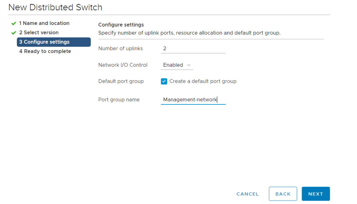
Review the configuration and click Finish to create the distributed switch.
After creating the distributed switch, right click on the switch and select the Add and Manage Hosts.
On the Select Task page, select the task as Add hosts and click Next .
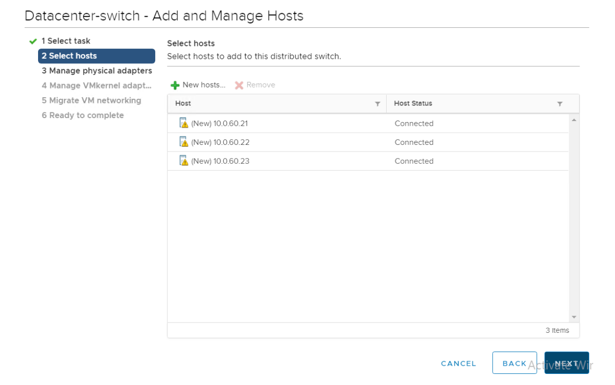
From the select hosts page, click + new hosts and select all the vSphere hosts within the cluster to be configured with the distributed switch and click OK.
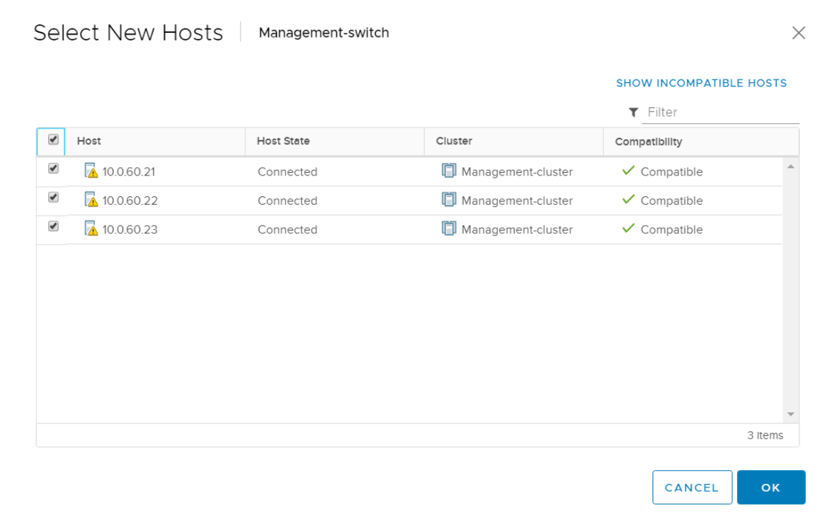
- Verify the required hosts are added and click Next.
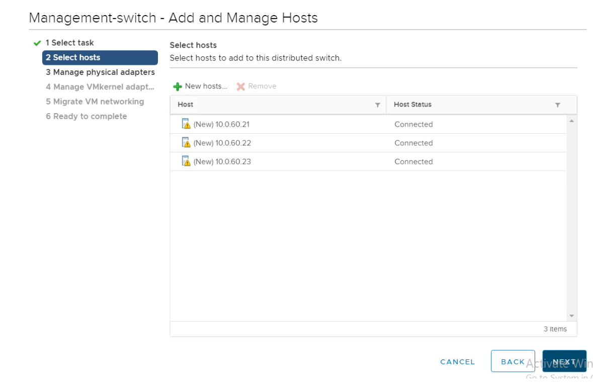
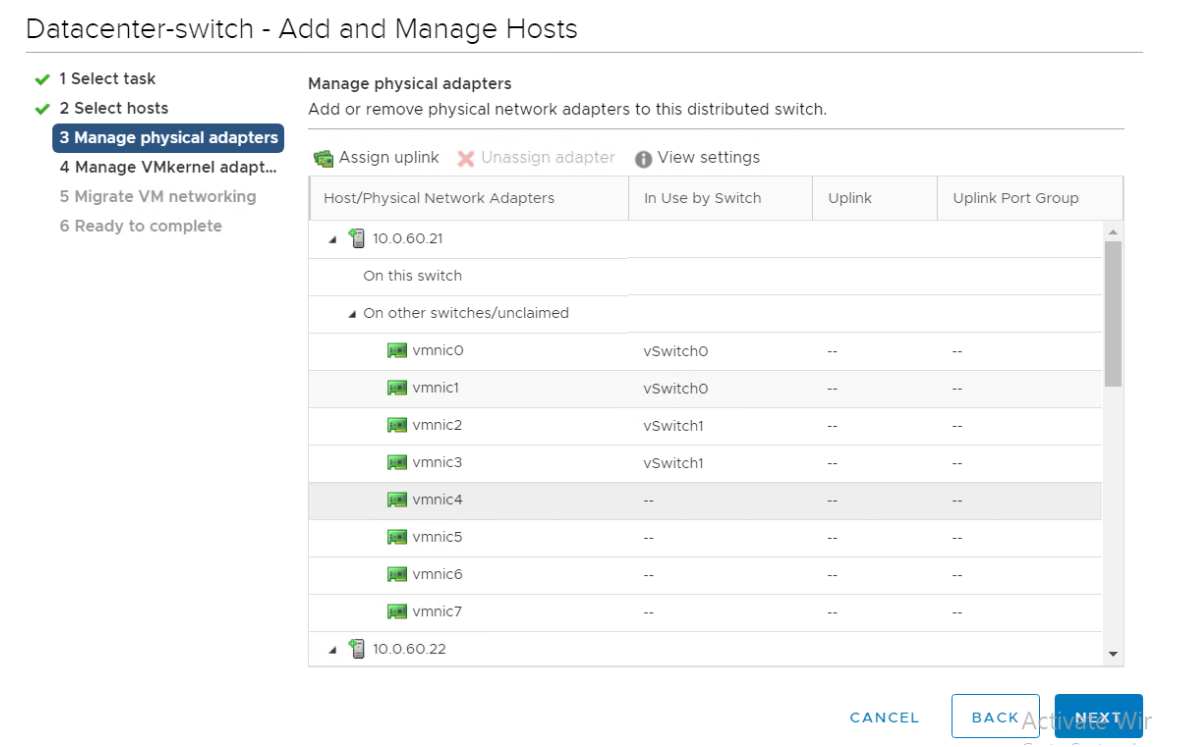
In the Manage Physical Adapters page, select the Physical Network Adapter in each host for the corresponding network being configured and click Assign uplink. Click Next.
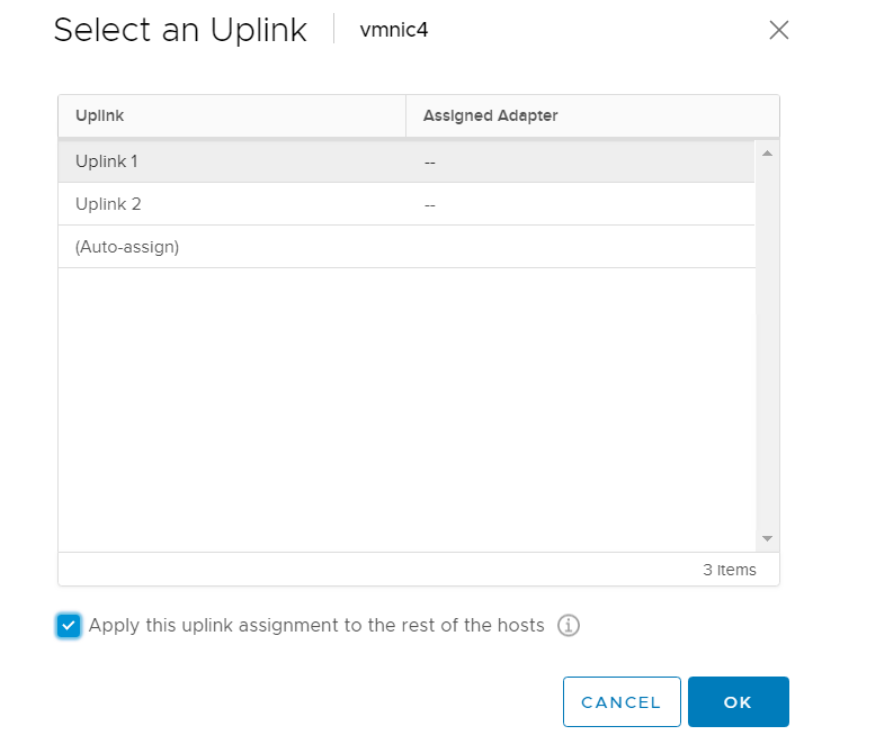
Choose the Uplink and select Apply this uplink assignment to the rest of the hosts. Select OK.
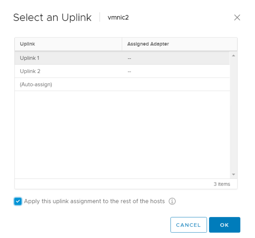
After the uplinks are assigned to the physical network adapters, select Next.
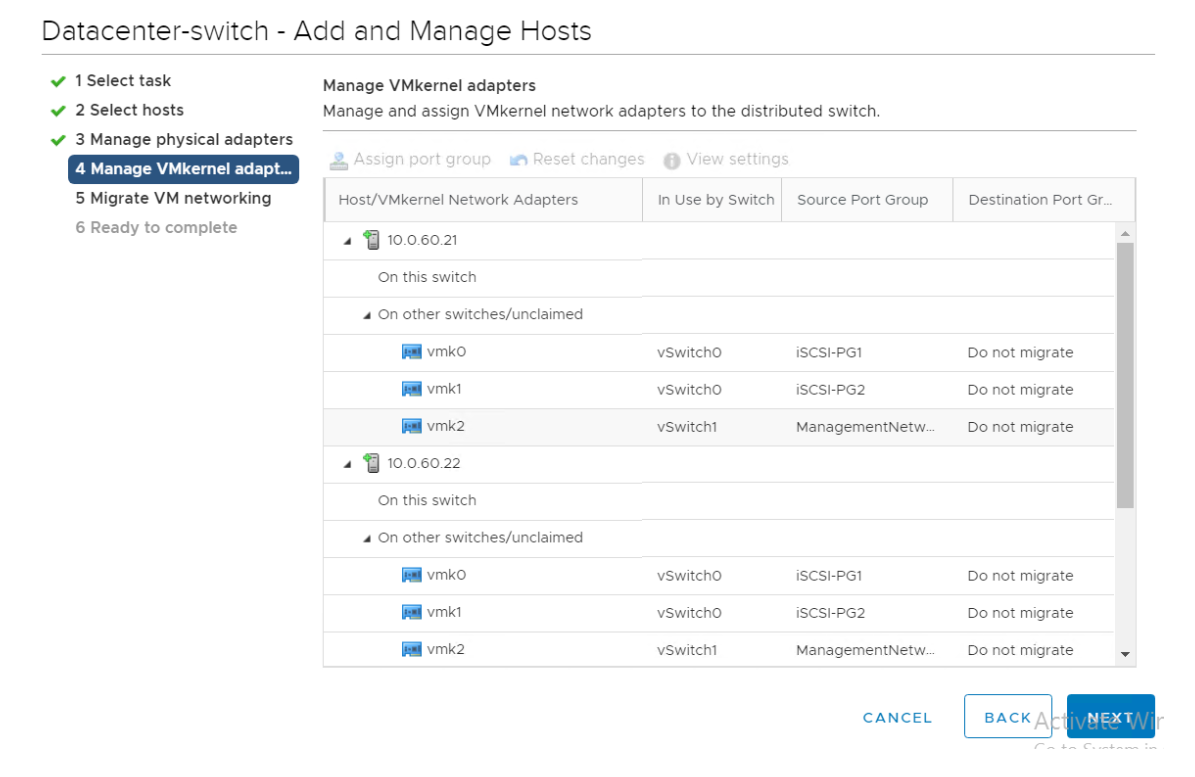
In the Manage VMkernel adapters, select the VMkernel to be migrated and click Assign port group.
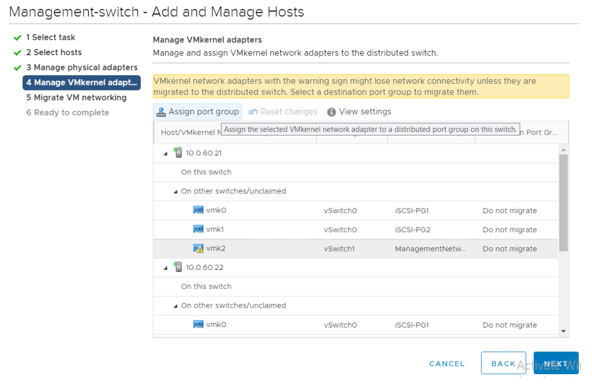
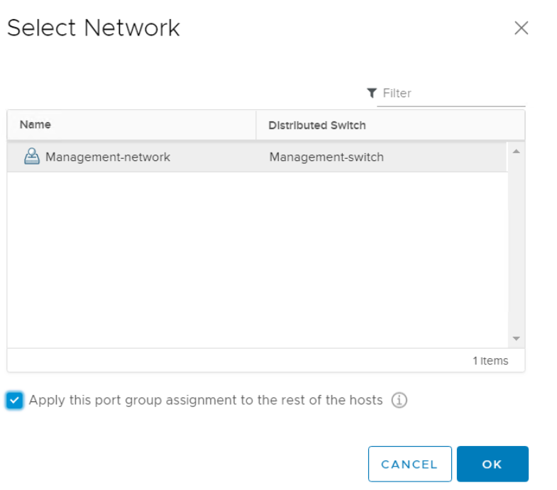
- Select the network associated with the VMkernel adapter which was selected in step 13 and click OK.
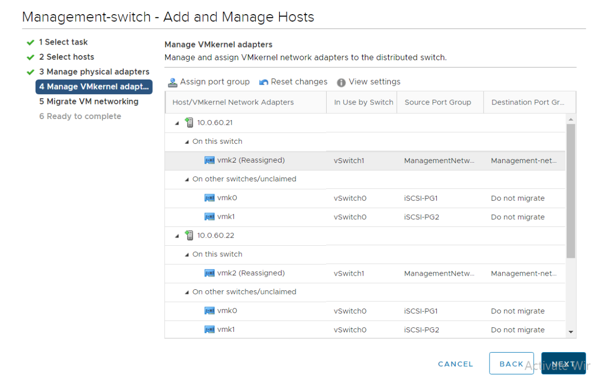
- Review the VMkernel adapter configuration performed in step 13 and 14, and click Next.
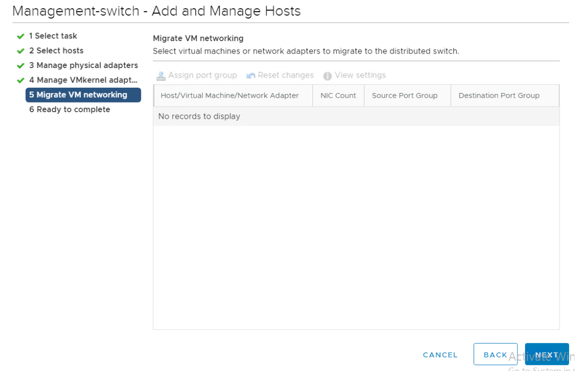
- Review the configuration in Migrate VM networking and click Next.
- In the Ready to complete page, review the configuration and click Finish.
# Configuring the iSCSI target server
Select the vSphere host and navigate to Configure -> Storage -> Storage Adapters -> iSCSI Adapter -> Dynamic Discovery .
Click the "+ Add..." icon to add the HPE Nimble Storage discovery IP address.
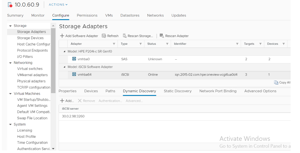
- Provide the Discovery IP address of HPE Nimble Storage system along with the port number and select the Inherit authentication settings from parent check box. Click OK.

- Repeat steps 1-3 in all hosts to add all the iSCSI target servers from the HPE Nimble Storage.
# Configuring the network port binding for iSCSI network
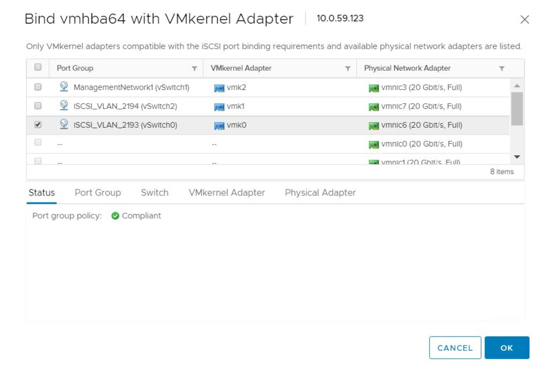
To configure Network Port Binding, navigate to Configure -> Storage -> Storage Adapters -> iSCSI Adapter -> Network Port Binding.
Click "+ Add Storage Adapter ".

- Select the Port Group of the iSCSI A network and click OK.
- Select Port Group of the iSCSI B network and click OK.
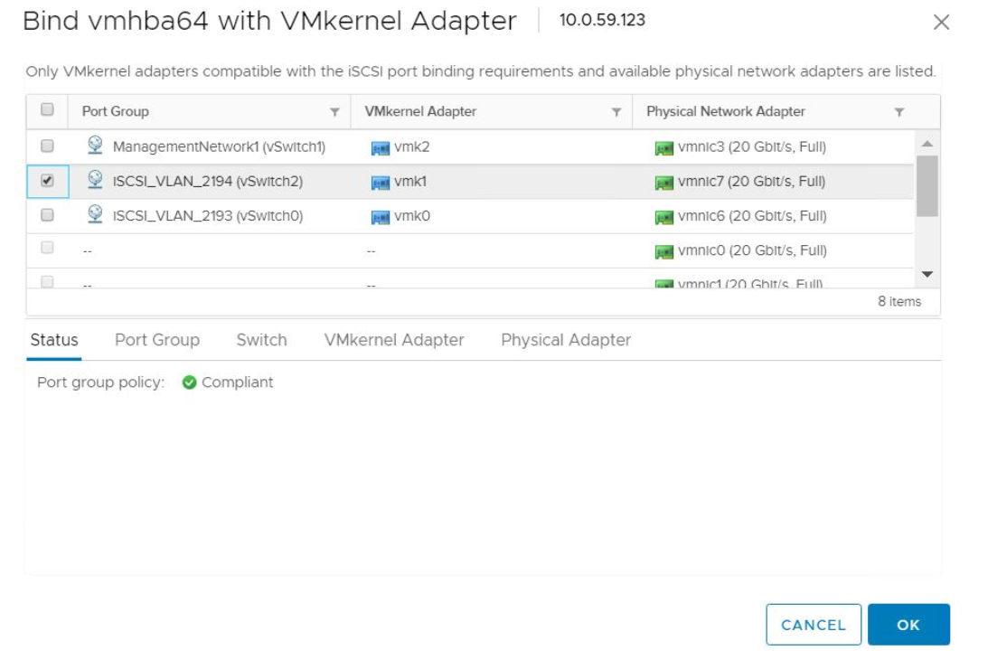
- Repeat the steps on all hosts for both iSCSI.
# Adding a datastore using HPE Nimble Storage volume in vCenter
A datastore needs to be created in VMware vCenter from the volume carved out of HPE Nimble Storage to store the VMs. The following steps create a datastore on the HPE Nimble Storage.
- From the vSphere Web Client navigator, right-click the cluster, select Storage from the drop-down menu, and then select New Datastore.
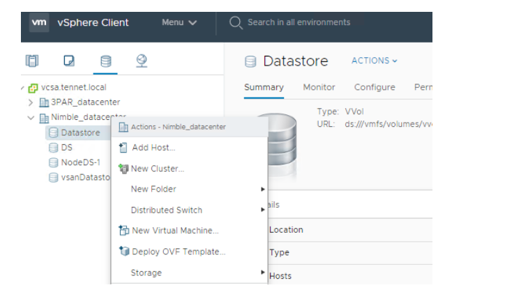
On the Type page, select VMFS as the Datastore type and click Next.
On the Name and Device selection page, provide the values requested and click Next.
Select a host to view its accessible disk/LUNs. Any of the hosts that are associated with the HPE Nimble Storage volume may be selected and click Next.
Select the Volume from HPE Nimble Storage and click Next.
From the VMFS version page, select VMFS 6 and click Next.
Specify details for Partition configuration and click Next. By default, the entire free space on the storage device is allocated. You can customize the space if required.
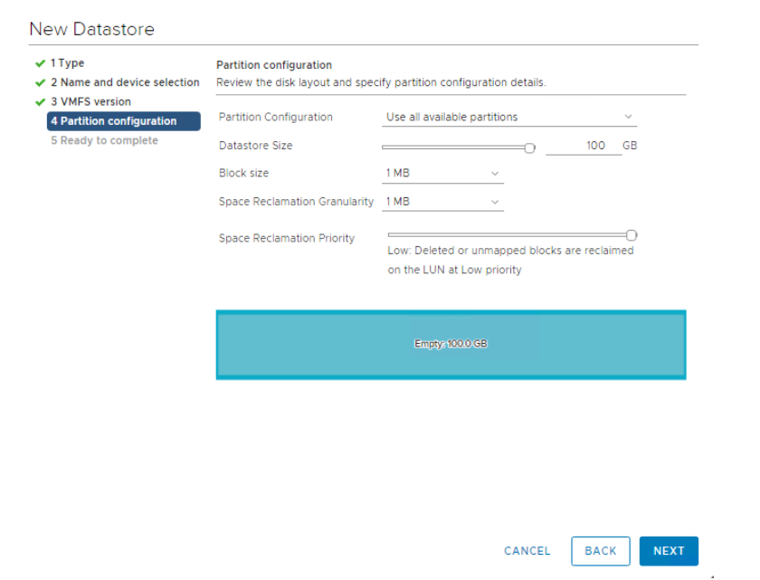
- On the Ready to complete page, review the datastore configuration and click Finish.
Note
If you are utilizing virtual worker nodes, repeat this section to create a datastore to store the worker node virtual machines.
# Deploying vSphere hosts
Refer to the Server Profiles section in this document to create the server profile for the vSphere hosts.
After the successful creation of the server profile, install the hypervisor. The following steps describe the process to install the hypervisor:
From the HPE OneView interface, navigate to Server Profiles and select ESXi-empty-volume Server Profile, Select Actions > Launch Console.
From the Remote Console window, choose Virtual Drives -> Image File CD-ROM/DVD from the iLO options menu bar.
Navigate to the VMware ESXi 6.7 ISO file located on the installation system. Select the ISO file and click Open.
If the server is in the powered off state, power switch on the server by selecting Power Switch -> Momentary Press.
During boot, press F11 Boot Menu and select iLO Virtual USB 3: iLO Virtual CD-ROM.
When the VMware ESXi installation media has finished loading, proceed through the VMware user prompts. For storage device, select the 40GiB OS volume created on the HPE Image Streamer during server profile creation and set the root password.
Wait until the vSphere installation is complete.
After the installation is complete, press F2 to enter the vSphere host configuration page and update the IP address, gateway, DNS, hostname of the host and enable SSH.
After the host is reachable, proceed with the next section.
# HPE OneView for VMware vCenter
HPE OneView for VMware vCenter is a single, integrated plug-in application for VMware vCenter management. This enables the vSphere administrator to quickly obtain context-aware information about HPE Servers and HPE Storage in their VMware vSphere data center directly from within vCenter. This application enables the vSphere administrator to easily manage physical servers and storage, datastores, and virtual machines. By providing the ability to clearly view and directly manage the HPE Infrastructure from within the vCenter console, the productivity of VMware administrator increases. This also enhances the ability to ensure quality of service.
For more details, refer to the HPE documentation at https://h20392.www2.hpe.com/portal/swdepot/displayProductInfo.do?productNumber=HPVPR (opens new window).
# Creating the Data center, Cluster and adding hosts in VMware vCenter
This section assumes a VMware vCenter server is available within the installation environment. A data center is a structure in VMware vCenter which contains clusters, hosts, and datastore. To begin with, a data center needs to be created, followed by the clusters and adding hosts into the clusters.
To create a data center, a cluster enabled with vSAN and DRS and adding hosts, the installation user will need to edit the vault file and the variables YAML file. Using an editor, open the file /etc/ansible/hpe-solutions-openshift/synergy/scalable/vsphere/vcenter/roles/prepare_vcenter/vars/main.yml to provide the names for data center, clusters and vSphere hostnames. A sample input file is listed and as follows. Installation user should modify this file to suit the environment.
In the Ansible vault file (secret.yml) found at /etc/ansible/hpe-solutions-openshift/synergy/scalable/vsphere/vcenter, provide the vCenter and the vSphere host credentials.
# vsphere hosts credentials

vsphere_username: <username>

vsphere_password: <password>

# vcenter hostname/ip address and credentials

vcenter_hostname: x.x.x.x

vcenter_username: <username>

vcenter_password: <password>
Note
This section assumes all the virtualization hosts have a common user name and password. If it does not have a common username and password, it is up to the installation user to add the virtualization hosts within the appropriate cluster.
Variables for running the playbook can be found at /etc/ansible/hpe-solutions-openshift/synergy/scalable/vsphere/vcenter/roles/prepare_vcenter/vars/main.yml.
# custom name for data center to be created.

datacenter_name: datacenter

# custom name of the compute clusters with the ESXi hosts for Management VMs.

management_cluster_name: management-cluster

# hostname or IP address of the vsphere hosts utilized for the management nodes.

vsphere_host_01: 10.0.x.x

vsphere_host_02: 10.0.x.x

vsphere_host_03: 10.0.x.x
After the variable files are updated with the appropriate values, execute the following command within the installer VM to create the data center, clusters, and add hosts into respective clusters.
> cd /etc/ansible/hpe-solutions-openshift/synergy/scalable/vsphere/vcenter/

> ansible-playbook playbooks/prepare_vcenter.yml –ask-vault-pass
# Configuring the network
Distributed switches need to be configured to handle the vSphere and VM traffic over the management, data center, and iSCSI network present in the environment. This section consists of:
Configuring distributed switches for the data center and iSCSI networks.
Migrating from a standard switch to a distributed switch for management network.
Configuring the iSCSI target server.
Configuring the network port binding for iSCSI networks.
# Configuring distributed switches for data center and iSCSI network
- Login to vCenter. Navigate to Networking -> -> Distributed Switch -> New Distributed Switch.

From the New Distributed Switch page, provide a suitable Name for the switch and click Next.
Select the version for the distributed switch as 6.6.0 and click Next.
On the Configure settings page, provide the following information as shown and click Next:
a. Number of uplinks (2 uplinks for management networks and 1 uplink each for the iSCSI network).
b. Enable Network I/O control.
c. Select the Create a default port group option and provide unique names for the corresponding network.
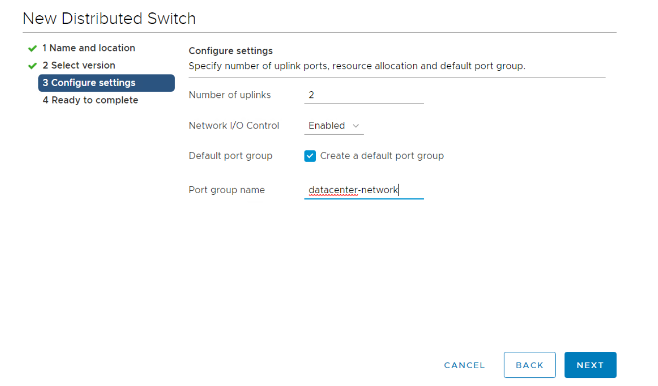
- Review the configuration as shown and click Finish to create the distributed switch.
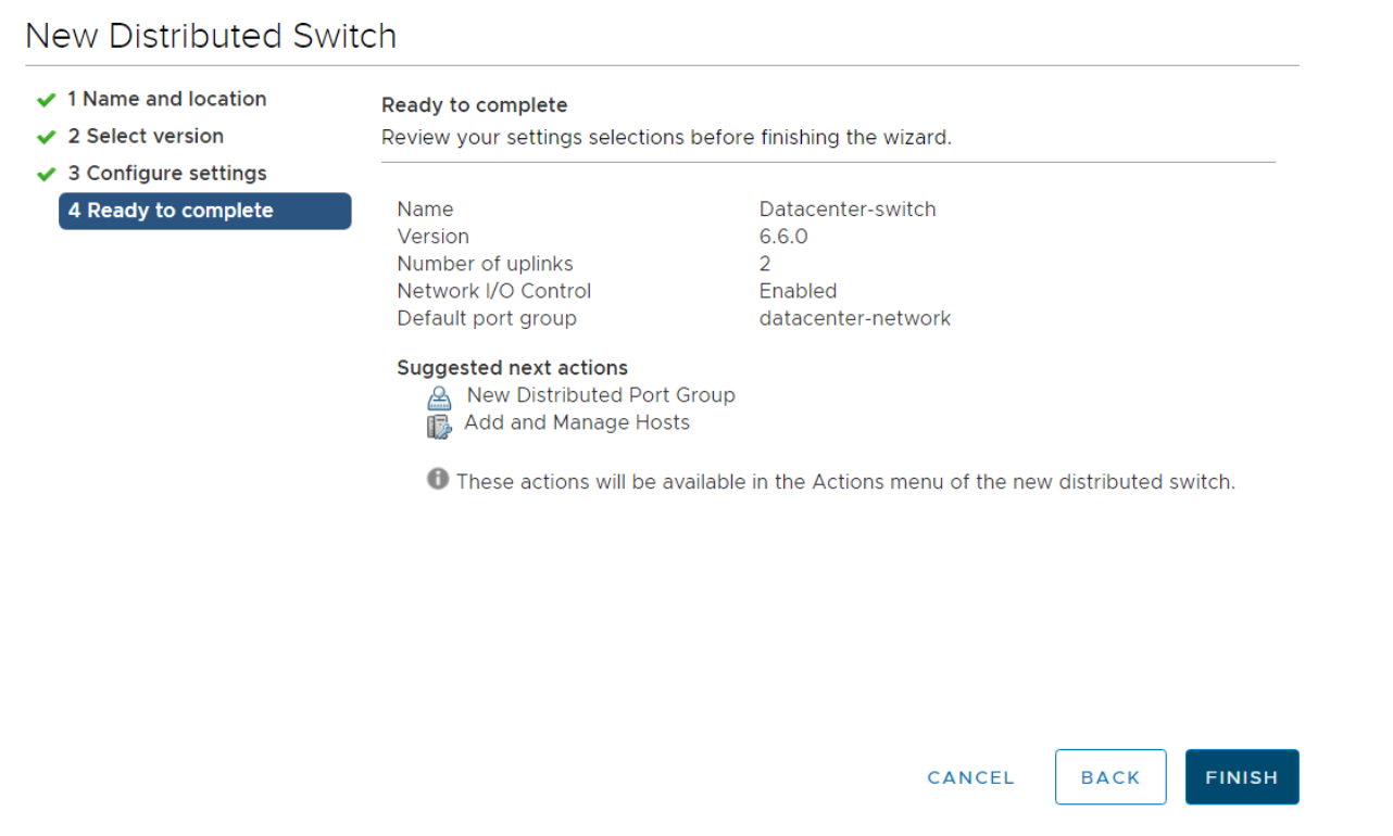
- After creating the distributed switch, right click on the switch and select Add and Manage Hosts.

In the select task page, select the task as Add hosts and click Next.
From the select host page, click + new hosts and select all the vSphere hosts within the cluster to be configured with the distributed switch and click OK.
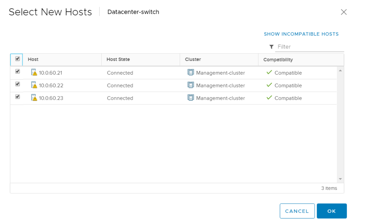
- Verify that the required hosts are added and click Next.
- In the Manage Physical Adapters page, select the Physical Network Adapters in each host for the corresponding network being configured and click Assign uplink as shown.
- Choose the uplink and select Apply this uplink assignment to the rest of the hosts. Select OK.
After the uplinks are assigned to the physical adapters, select Next.
Review the configurations in the Manage VMkernel adapters and click Next.
- Review the configuration in Migrate VM networking and click Next.
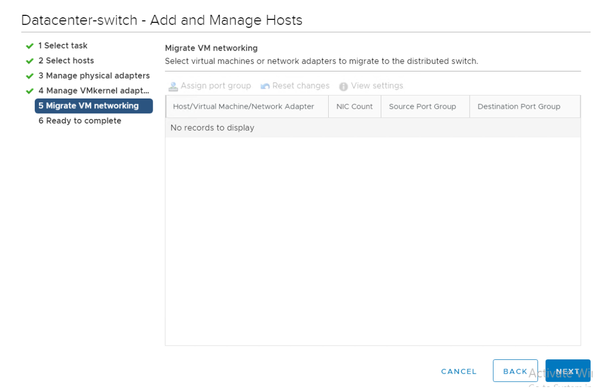
On the Ready to complete page, review the configuration and click Finish.
To add VMkernel adapter to the distributed switch, navigate to Networking -> -> -> Add VMkernel Adapter.
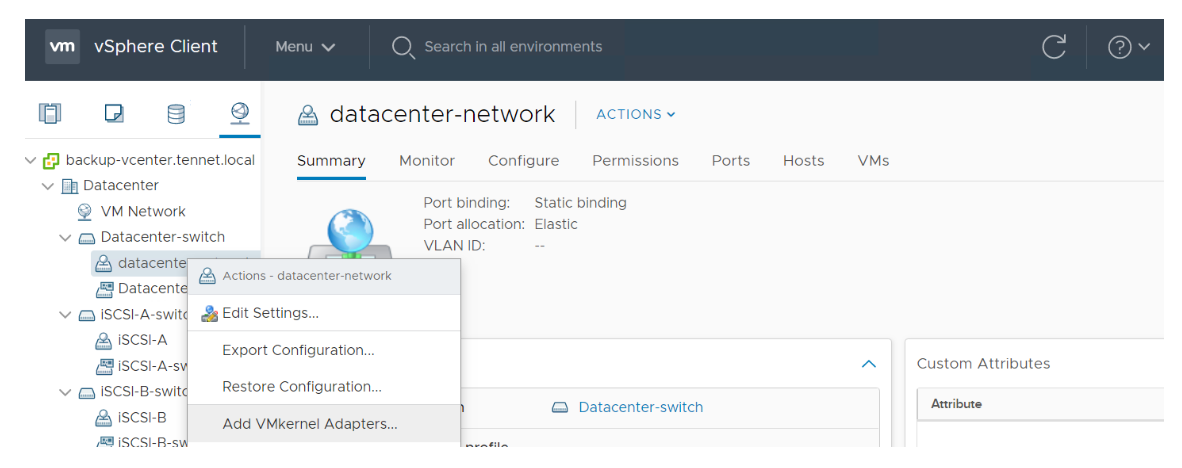
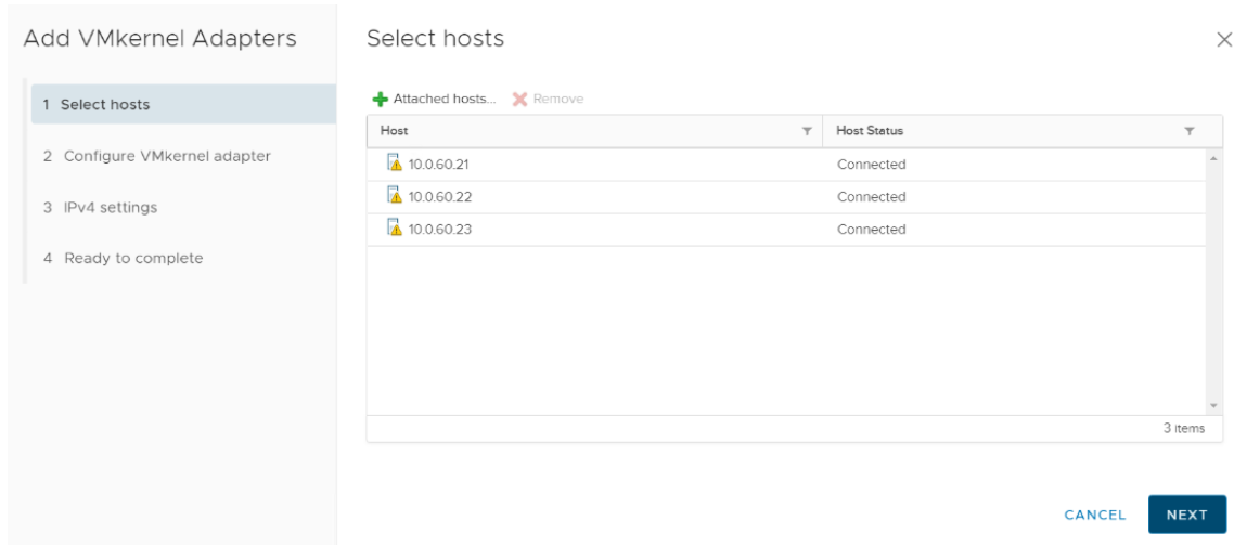
- Select the hosts to which the configuration needs to be applied and click Next.
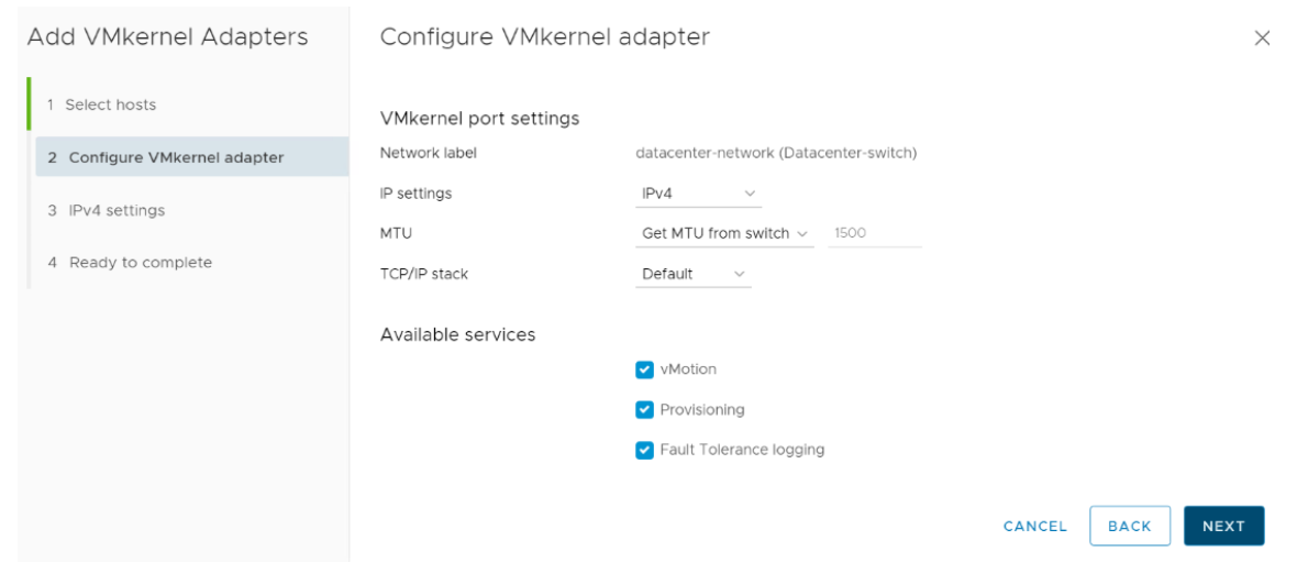
- In the configure VM kernel adapter page, select the IP settings as IPv4 and apply the appropriate services and then click Next. This should include vMotion and Fault Tolerance logging at a minimum.
- In the IPv4 settings page, provide the network settings and gateway settings for the all the hosts and click Next.
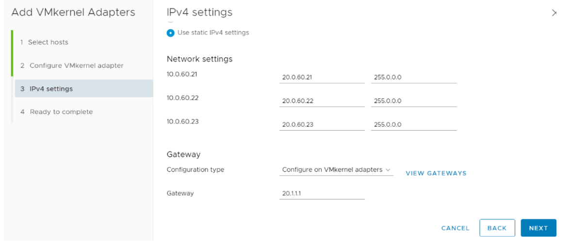
- Review the settings in the Ready to complete page and click Finish.
Note
Repeat the Configuring Distributed Switches section for all the iSCSI network.
# Creating a Datastore in vCenter
A datastore needs to be created in VMware vCenter from the volume carved out of HPE Storage SANs to store the VMs. The following are the steps to create a datastore in vCenter.
From the vSphere Web Client navigator, right-click the cluster, select Storage from the menu, and then select the New Datastore.
From the Type page, select VMFS as the Datastore type and click Next.
Enter the datastore name and if necessary, select the placement location for the datastore and click Next.
Select the device to use for the datastore and click Next.
From VMFS version page, select VMFS 6 and click Next.
Define the following configuration requirements for the datastore as per the installation environment and click Next.
a. Specify partition configuration
b. Datastore Size
c. Block Size
d. Space Reclamation Granularity
e. Space Reclamation Priority
On the Ready to complete page, review the Datastore configuration and click Finish.
Note
If you utilize virtual worker nodes, repeat this section to create a Datastore to store the worker virtual machines.
# Red Hat OpenShift Container Platform sizing
Red Hat OpenShift Container Platform sizing varies depending on the requirements of the organization and type of deployment. This section highlights the host sizing details recommended by Red Hat.
| Resource | Bootstrap node | Master node | Worker node |
|---|---|---|---|
| CPU | 4 | 4 | 4 |
| Memory | 16GB | 16GB | 16GB |
| Disk storage | 120GB | 120GB | 120GB |
| Disk storage | 120GB | 120GB | 120GB |
Disk partitions on each of the nodes are as follows.
/var – 40GB
/usr/local/bin – 1GB
Temporary directory – 1GB
Note
Sizing for worker nodes is ultimately dependent on the container workloads and their CPU, memory, and disk requirements.
For more information about Red Hat OpenShift Container Platform sizing, refer to the Red Hat OpenShift Container Platform 4 product documentation at https://access.redhat.com/documentation/en-us/openshift_container_platform/4.4/html/scalability_and_performance/index (opens new window).