# Physical Environment components
This section outlines the steps to be performed to configure the physical environment used in this solution
# Cabling the HPE Synergy 12000 Frame and HPE Virtual Connect 100Gb SE F8 Modules for HPE Synergy
This section shows the physical cabling between frames, Virtual Connect modules and solution switching. It is intended to provide an understanding of how the infrastructure was interconnected during testing and to serve as a guide on which the installation user can base their configuration.
Figure 6 describes the cabling configuration of the three (3) HPE Synergy 12000 Frames as well as the HPE FlexFabric 5945 Switches and Intelligent Resilient Fabric (IRF) within the context of this solution. These cables carry frame management, inter-frame and interconnect traffic between frames.

Figure 6. Frame and switch cabling within the solution
# Cabling the HPE Synergy 12000 Frame to Fibre Channel 5945 switch
HPE 3PAR StoreServ 8440 Storage provides shared and dedicated storage for a variety of purposes within this solution including housing virtual machines and persistent volume. Figure 7 shows the cabling of the HPE Synergy 12000 frames to the HPE Fibre Channel switching utilized in this solution.
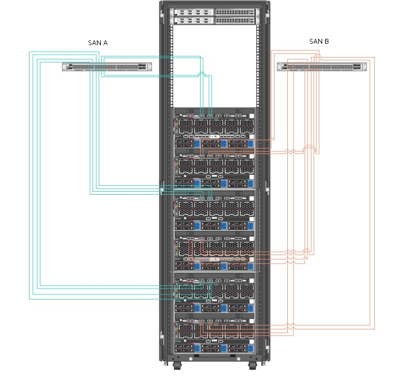
Figure 7. Cabling of HPE Synergy interconnects and HPE SN6600B switching
Table 7 describes the cabling from the HPE Synergy 12000 Frames to the HPE SN6600B Fibre Channel switches.
Table 7. Cabling between HPE Synergy and HPE SN6600B switching
| Source Port (Frame) | Destination Port (Switch) |
|---|---|
| Frame 1, ICM 2, Port 1 | SAN Switch A, Port 10 |
| Frame 1, ICM 2, Port 2 | SAN Switch A, Port 11 |
| Frame 1, ICM 2, Port 3 | SAN Switch A, Port 16 |
| Frame 1, ICM 2, Port 4 | SAN Switch A, Port 17 |
| Frame 1, ICM 5, Port 1 | SAN Switch B, Port 10 |
| Frame 1, ICM 5, Port 2 | SAN Switch B, Port 11 |
| Frame 1, ICM 5, Port 3 | SAN Switch B, Port 16 |
| Frame 1, ICM 5, Port 4 | SAN Switch B, Port 17 |
| Frame 2, ICM 2, Port 1 | SAN Switch A, Port 14 |
| Frame 2, ICM 2, Port 2 | SAN Switch A, Port 15 |
| Frame 2, ICM 2, Port 3 | SAN Switch A, Port 20 |
| Frame 2, ICM 2, Port 4 | SAN Switch A, Port 21 |
| Frame 2, ICM 5, Port 1 | SAN Switch B, Port 14 |
| Frame 2, ICM 5, Port 2 | SAN Switch B, Port 15 |
| Frame 2, ICM 5, Port 3 | SAN Switch B, Port 20 |
| Frame 2, ICM 5, Port 4 | SAN Switch B, Port 21 |
| Frame 3, ICM 2, Port 1 | SAN Switch A, Port 18 |
| Frame 3, ICM 2, Port 2 | SAN Switch A, Port 19 |
| Frame 3, ICM 2, Port 3 | SAN Switch A, Port 22 |
| Frame 3, ICM 2, Port 4 | SAN Switch A, Port 23 |
| Frame 3, ICM 2, Port 4 | SAN Switch A, Port 23 |
| Frame 3, ICM 5, Port 1 | SAN Switch B, Port 18 |
| Frame 3, ICM 5, Port 2 | SAN Switch B, Port 19 |
| Frame 3, ICM 5, Port 3 | SAN Switch B, Port 22 |
| Frame 3, ICM 5, Port 4 | SAN Switch B, Port 23 |
Table 8 describes the connectivity of the HPE 3PAR StoreServ 8440 controllers to the HPE SN6600B SAN switching.
Table 8. HPE 3PAR StoreServ 8440 Controller to SAN
| Source Port (HPE 3PAR) | Destination Port (Switch) |
|---|---|
| Node 0, S2P1 | SAN Switch A, Port 8 |
| Node 0, S2P2 | SAN Switch B, Port 8 |
| Node 1, S2P1 | SAN Switch A, Port 12 |
| Node 1, S2P2 | SAN Switch B, Port 12 |
| Node 2, S2P1 | SAN Switch A, Port 9 |
| Node 2, S2P2 | SAN Switch B, Port 9 |
| Node 3, S2P1 | SAN Switch A, Port 13 |
| Node 3, S2P2 | SAN Switch B, Port 13 |
# Cabling between HPE Synergy 12000 Frame to 3PAR 5945 switch
The HPE 3PAR StoreServ 8440 Storage used in this solution provides shared and dedicated storage for a variety of purposes within this solution including virtual machine hosting, registry storage and persistent volume for containers. Figure 8 shows the cabling of the HPE 3PAR StoreServ 8440 Storage to the HPE switching utilized in this solution. Note that this diagram shows the storage and switching in the same rack to provide clarity. As implemented for this solution, the switching resided in the HPE Synergy rack. The blue and purple wires in the Figure 8 represent the separate iSCSI VLANs. In this solution, we have used one HPE 3PAR StoreServ Storage. Optionally, two HPE 3PAR StoreServ Storage can be used to provide replication.
# HPE Nimble iSCSI
A HPE Nimble Storage AF40 array provides shared and dedicated storage for a variety of purposes within this solution.
Figure 8 describes the cabling configuration of the three (3) HPE Synergy 12000 Frames as well as the HPE FlexFabric 5945 Switches and Intelligent Resilient Fabric (IRF) within the context of this solution. These cables carry frame management, inter-frame and interconnect traffic between frames.
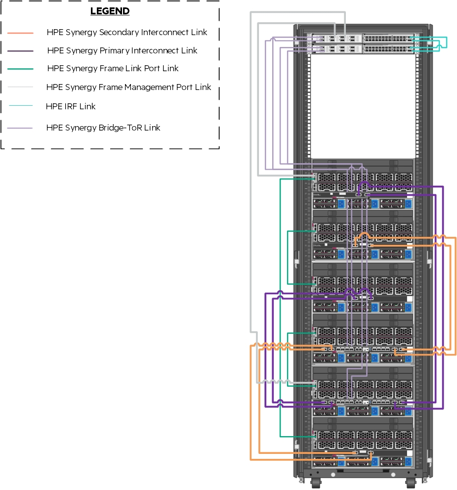
Figure 8. Frame and switch cabling within the solution
Figure 9 shows the cabling of HPE Synergy Frames to the network switches. At the lowest level, there are four (4) 100GbE connections dedicated to carrying redundant, production network traffic to the first layer switch where it is further distributed. iSCSI traffic is separated into two (2) VLANs and is carried to the first network switch pair over two (2) 100GbE links per VLAN. Unlike the Ethernet traffic which is distributed between the switches, each iSCSI VLAN is sent directly to one switch configured with a pair of access ports.
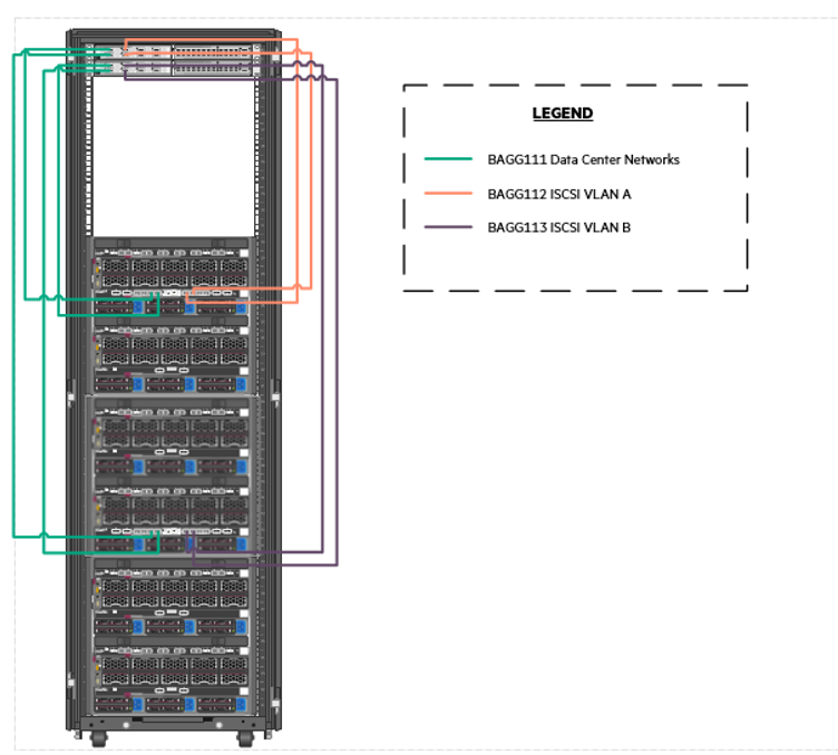
Figure 9. Cabling of the HPE Synergy interconnects to the HPE FlexFabric 5945 switches
Figure 9 shows the cabling of the HPE Nimble Storage AF40 to the HPE switching utilized in this solution. Note that this diagram shows the storage and switching in the same rack to provide clarity. As implemented for this solution, the switching resided in the HPE Synergy rack. The orange and purple wires in the figure represent the separate iSCSI VLANs.
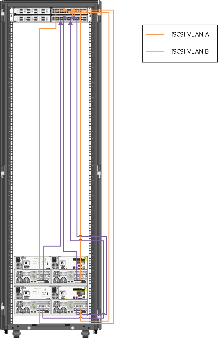
Figure 10. Cabling of the HPE Nimble Storage arrays to the HPE FF 5940 switches
# Networking
Figure 10 documents the cabling of the solution from the HPE Virtual Connect SE 100 GB modules to the switches. All egressing Ethernet networks are carried on a single bridge-aggregation group (BAGG). Top of rack switching was used in the creation of this solution, but end of row switching is equally effective in HPE Synergy environments and can reduce overall solution costs by reducing the number of physical switches.
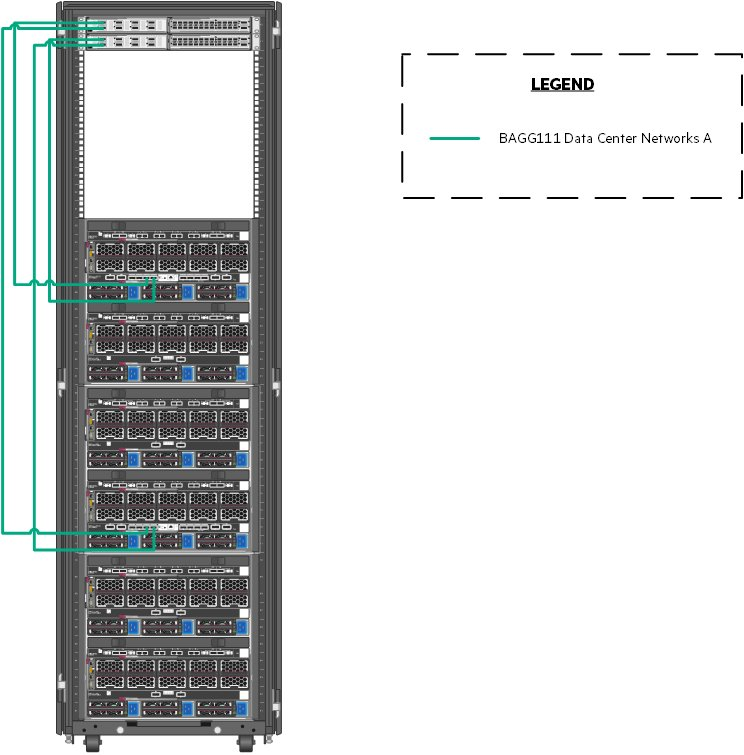
Figure 11. Network cabling from the HPE Synergy 12000 Frames to the switches
Table 9 describes the configuration of the network as defined within HPE OneView for HPE Synergy and the bandwidth associated with each network. Network is carried outbound on a single BAGG except the Synergy Management network.
Table 9. Network defined within HPE OneView for HPE Synergy
| Network Name | Type | VLAN Number | Purpose | Requested Bandwidth (Gb) | Maximum Bandwidth (Gb) |
|---|---|---|---|---|---|
| Management | Ethernet | 1193 | Solution management | 5 | 40 |
| Data_Center | Ethernet | 2193 | Application access and authentication | 10 | 40 |
| iSCSI_VLAN_A | Ethernet | 3193 | iSCSI_VLAN_A | 10 | 50 |
| iSCSI_VLAN_B | Ethernet | 3194 | iSCSI_VLAN_B | 10 | 50 |
Table 10 explains the cabling of the Virtual Connect interconnect modules to the HPE FlexFabric 5945 switching.
Table 10. Networks used in this solution.
| Uplink Set | Synergy Source | Switch Destination |
|---|---|---|
| Network | Enclosure 1 Port Q3 | HundredGigE1/1/1 |
| Enclosure 1 Port Q4 | HundredGigE2/1/1 | |
| Enclosure 2 Port Q3 | HundredGigE1/1/2 | |
| Enclosure 2 Port Q4 | HundredGigE2/1/2 | |
| iSCSI_SAN_A | Enclosure 1 Port Q5 | HundredGigE1/1/5 |
| Enclosure 1 Port Q6 | HundredGigE1/1/6 | |
| iSCSI_SAN_B | Enclosure 2 Port Q5 | HundredGigE2/1/5 |
| Enclosure 2 Port Q6 | HundredGigE2/1/6 |
Utilizing HPE Synergy, the network within the solution can traverse the HPE Synergy infrastructure in an east-west fashion across high speed, low latency links both within and between HPE Virtual Connect Modules. The communication between the Red Hat OpenShift Container Platform 4.6 management pieces remains within the HPE Synergy Frames.
# Configuring the solution switching
The solution described in this document utilized HPE FlexFabric 5945 switches. The HPE FlexFabric 5945 switches are configured according to the configuration parameters found later in this section. The switches should be configured with an HPE Intelligent Resilient Framework (IRF). To understand the process of configuring IRF, refer the HPE FlexFabric 5945 Switch Series Installation Guide at https://support.hpe.com/hpsc/doc/public/display?sp4ts.oid=null&docLocale=en_US&docId=emr_na-c05212026 (opens new window). This guide may also be used to understand the initial installation of switching, creation of user accounts and access methods. The remainder of this section is built with the assumption that the switch has been installed, configured for IRF, hardened, and is accessible over SSH.
NOTE
HPE Synergy facilitates the use of end of row switching to reduce switch and port counts in the context of the solution. If end of row switching is chosen, then this section should be used as guidance for how to route network traffic outside of the HPE Synergy Frames.
# Physical cabling
Table 11 is a map of source ports to ports on the HPE FlexFabric 5945 switches.
Table 11. HPE FlexFabric 5945 port map
| Source Port | Switch Port |
|---|---|
| Nimble Management Port Eth1 | TenGigE1/2/17 |
| Nimble Controller A TG1 | TenGigE1/2/13 |
| Nimble Controller A TG2 | TenGigE2/2/13 |
| Nimble Controller B TG1 | TenGigE1/2/14 |
| Nimble Controller B TG2 | TenGigE2/2/14 |
| Nimble Replication Port Eth2 | TenGigE1/2/15 |
| Virtual Connect Frame U30, Q3 | HundredGigE1/1/1 |
| Virtual Connect Frame U30, Q4 | HundredGigE2/1/1 |
| Virtual Connect Frame U30, Q5 | HundredGigE1/1/5 |
| Virtual Connect Frame U30, Q6 | HundredGigE1/1/6 |
| Virtual Connect Frame U40, Q3 | HundredGigE1/1/2 |
| Virtual Connect Frame U40, Q4 | HundredGigE2/1/2 |
| Virtual Connect Frame U40, Q5 | HundredGigE2/1/5 |
| Virtual Connect Frame U40, Q6 | HundredGigE2/1/6 |
| To Upstream Switching | Customer Choice |
Hewlett Packard Enterprise recommended that the installation user logs on to the switch post-configuration and provides a description for each of these ports.
# Network definition
There are multiple networks defined in this solution:
Management Network -- This network facilitates the management of hardware and software interfaced by IT.
Data Center Network -- This network carries traffic from the overlay network used by the pods to external consumers of pod deployed services.
iSCSI Network -- This network consists of two separate network segments that provide a redundant path for iSCSI storage traffic within the solution.
Table 12 defines the VLANs configured using HPE Synergy Composer in the creation of this solution. These networks should be defined at both the first layer switch and within Composer. This solution utilizes unique VLANs for the data center and solution management segments. Actual VLANs and network count will be determined by the requirements of your production environment.
Table 12. Networks used in this solution.
| Network Function | VLAN Number | Bridge Aggregation Group |
|---|---|---|
| Solution_Management | 1193 | 111 |
| Data_Center | 2193 | 111 |
| iSCSI_A | 3193 | 112 |
| iSCSI_B | 3194 | 113 |
To add these networks to the switch, log on to the switch console over SSH and run the following commands.
> sys
> vlan 1193 2193 3193 3194
For each of these VLANs, perform the following steps.
> interface vlan-interface ####
> name VLAN Name per table above
> description Add text that describes the purpose of the VLAN
> quit
NOTE
It is strongly recommended to configure a dummy VLAN on the switches and assign unused ports to that VLAN.
The switches should be configured with a bridge aggregation group (BAGG) for the different links to the HPE Synergy Frame connections. To configure the BAGG and ports as described in Table 12, run the following commands.
> interface Bridge-Aggregation111
> link-aggregation mode dynamic
> description <FrameNameU30>-ICM
> quit

> interface range name <FrameNameU30>-ICM interface Bridge-Aggregation111
> quit

> interface range HundredGigE 1/1/1 to HundredGigE 1/1/2 HundredGigE 2/1/1 to HundredGigE 2/1/2
> port link-aggregation group 111
> quit

> interface range name <FrameNameU30>-ICM
> port link-type trunk
> undo port trunk permit vlan 1
> port trunk permit vlan 193 1193 2193
> quit
3). After the configuration of the switches is complete, save the state and apply it by typing save and follow the resulting prompts.
# HPE Synergy 480 Gen10 Compute Modules
This section describes the connectivity of the HPE Synergy 480 Gen10 Compute Modules used in the creation of this solution. The HPE Synergy 480 Gen10 Compute Modules, regardless of function, were all configured identically. Table 13 describes the host configuration tested for this solution. Server configuration should be based on customer needs and the configuration used in the creation of this solution might not align with the requirements of any given production implementation.
Table 13. Host configuration
| Component | Quantity |
|---|---|
| HPE Synergy 480/660 Gen10 Intel Xeon-Gold 6130 (2.1GHz/16-core/125W) FIO Processor Kit | 2 per server |
| HPE 8GB (1x 8GB) Single Rank x8 DDR4-2666 CAS-19-19 Registered Smart Memory Kit | 20 per server |
| HPE 16GB (1x 16GB) Single Rank x4 DDR4-2666 CAS-19-19 Registered Smart Memory Kit | 4 per server |
| HPE Synergy 3820C 10/20Gb Converged Network Adapter | 1 per server |
| HPE Smart Array P204i-c SR Gen10 12G SAS controller | 1 per server |
| HPE 1.92TB SATA 6GB Mixed Use SFF (2.5in) 3yr Warranty Digitally Signed Firmware SSD | 2 per management host |
# HPE Synergy integration with Cisco Application Centric Infrastructure (ACI)
# What is Cisco ACI?
Cisco® Application Centric Infrastructure (Cisco ACI™) is an industry-leading secure, open, and comprehensive Software-Defined Networking (SDN) solution. It radically simplifies, optimizes, and accelerates infrastructure deployment and governance and expedites the application deployment lifecycle.
Cisco ACI delivers an intent-based networking framework to enable agility in the data center. It captures high-level business and user intent in the form of a policy and translates this intent into the network constructs necessary to dynamically provision the network, security, and infrastructure services. It uses a holistic system-based approach, with tight integration between hardware and software and physical and virtual elements, an open ecosystem model, and innovative Cisco customer Application-Specific Integrated Circuits (ASICs) to enable unique business value for modern data centers. This unique approach uses a common policy-based operating model across the network, drastically reducing the cost and complexity of operating your network.
# Integration with HPE Synergy
This section specifies the reference to the technical whitepaper that will help the Data Center administrators to configure both baremetal OS and VMware ESXi hosts running on HPE Synergy compute nodes with Cisco ACI.
The two use cases where HPE Synergy can be integrated with Cisco ACI are:
- VMware virtual infrastructure integration with Cisco ACI to provide dynamic network provisioning. Baremetal OS installation on HPE Synergy compute nodes integrated with Cisco ACI.
For detailed information on integration of HPE Synergy with Cisco ACI, see
https://support.hpe.com/hpesc/public/docDisplay?docId=emr_na-a00003736en_us (opens new window)
# HPE Synergy Composer 2
At the core of the management of the HPE Synergy environment is HPE Synergy Composer 2. A pair of HPE Synergy Composers are deployed across frames to provide redundant management of the environment for both initial deployment and changes over the lifecycle of the solution. HPE Synergy Composer 2 is used to configure the environment prior to the deployment of the operating systems and applications.
This section walks the installation user through the process of installing and configuring the HPE Synergy Composer.
# Configure the HPE Synergy Composer via VNC
To configure HPE Synergy Composer with the user laptop, follow these steps:
Configure the laptop Ethernet port to the IP address 192.168.10.2/24. No gateway is required.
Use a CAT5e cable to connect the laptop computer Ethernet port to laptop port on a front panel module of HPE Synergy Composer.
Access the HPE Synergy Console using a web browser. Start a new browser session and enter http://192.168.10.1:5800 (opens new window).
Click Connect to start HPE OneView for Synergy from the HPE Synergy console.
Click Hardware Setup to connect with Installation Technician user privileges.
In the Appliance Network dialog box, fill in the following information.
a. Appliance host name: Enter a fully qualified name of the HPE Synergy Composer.
b. Address assignment: Manual
c. IP address: Enter an IP address on the management network.
d. Subnet mask or CIDR: Enter the subnet mask of the management network.
e. Gateway address: Enter the gateway for the management network.
f. Maintenance IP address 1: Enter a maintenance IP address on the management network.
g. Maintenance IP address 2: Enter a secondary maintenance IP address on the management network.
h. Preferred DNS server: Enter the DNS server.
i. IPv6 Address assignment: Unassign
Click OK.
When the hardware discovery process is complete, all HPE Synergy hardware including the Frames, Composer modules, Frame Link modules, Interconnect modules, Compute modules, and storage modules must be discovered and claimed by HPE OneView for Synergy.
Review and correct any issues listed in the hardware setup checklist. The HPE Synergy 12000 Frame Setup and Installation Guide available at http://www.hpe.com/info/synergy-docs (opens new window) provides troubleshooting steps for common issues during hardware setup.
Navigate to OneView -> Settings and then click Appliance. Verify that the active and standby appliances show a status of Connected.
# Configure appliance credentials
Log in to the HPE OneView for Synergy Web Administration Portal, review and accept the License Agreement.
On the HPE OneView Support Dialog box, verify that Authorized Service has a setting of Enabled. Click OK.
Log in as Administrator with default password admin, set the new password to <<composer_administrator_password>> and click Ok.
# Configure solution firmware
This solution adheres to the firmware recipe specified with the HPE Converged Solutions 750 specifications which can be found at CS750 Firmware and Software Compatibility Matrix. The solution used the latest firmware recipe available as of March 2020 including HPE OneView for Synergy 5.0:
HPE Synergy Firmware is regulated according to a given HPE Synergy software release, which includes the software version of HPE OneView for Synergy on HPE Synergy Composer and the HPE Synergy Custom SPP firmware bundle for all other HPE Synergy components. At this stage, update the HPE Synergy Composer. The guided setup takes care of the firmware updates to the remaining HPE Synergy components.
Select the OneView menu and select Settings.
Under Appliance, select Update Appliance and update Composer.
Once the update process completes, validate that both composer modules are connected and there is a green checkmark.
# Solution configuration
The installation user should utilize the Synergy Guided Setup to complete the following solution configuration details.
# Create additional users
It is recommended that you create a read-only user and an administrator account with a different username than administrator.
# Firmware
Upload a firmware bundle based on the HPE Converged Solutions 750 recipe. After the bundle starts uploading, proceed to additional steps without disrupting the upload.
# Create an IP pool on the management network
Follow the guidance to create an IP pool on the management network. This IP pool will provide IP addresses to management IP's and HPE device iLOs within the solution. Ensure that the pool is enabled prior to proceeding.
# Configure Ethernet networks
As explained in the Network definition section of this document, the solution utilizes three (3) network segments. Refer to the Create networks section of the OneView Guided Setup wizard to define the networks shown in Table 14 at a minimum. Your VLAN values will generally differ from those described below.
Table 14. Network defined within HPE Synergy Composer for this solution
| Network Name | VLAN Number | Purpose |
|---|---|---|
| Management | Ethernet | 1193 |
| Data_Center | Ethernet | 2193 |
The management network should be associated with the management network IP pool, which the user specified in the prior step. The installation user should create any additional required networks for the solution.
# Create Logical Interconnect Groups
Within Composer, use the Guided Setup to create a Logical Interconnect Group (LIG) with three (3) uplink sets defined. For this solution, the uplink sets are named Network. The uplink sets "Network" carries all other networks defined for the solution. Table 15 below defines the ports used to carry the uplink sets.
Table 15. Networks used in this solution
| Uplink Set | Synergy Source |
|---|---|
| Network | Enclosure 1, Bay 3, Port Q3 |
| Enclosure 1, Bay 3, Port Q4 | |
| Enclosure 2, Bay 6, Port Q3 | |
| Enclosure 2, Bay 6, Port Q4 |
# Create Enclosure Group
From the OneView Guided Setup, select Create enclosure group.
Provide a name and enter the number of frames.
Select Use address pool and utilize the management pool defined earlier.
Use the Logical Interconnect Group from the prior step in the creation of the Enclosure Group.
Select Create when ready.
# Create Logical Enclosure
Use the Guided Setup to create a logical enclosure making use of all three (3) enclosures. Select the firmware you uploaded earlier as a baseline. It can take some time for the firmware to update across the solution stack. Ensure that firmware complies with the baseline by selecting Actions and then Update Firmware. Click Cancel to exit.
# Configuring solution storage
The HPE Synergy D3940 Storage Module provides SSDs and optional Hard Disk Drives (HDDs) consumed by the Local Storage Operator, if not utilizing local disks within the HPE Synergy 480 Gen 10 Compute Modules. It can also provide boot volumes. HPE Nimble Storage and HPE 3PAR that dynamically provides Persistent Volume (PV) for containers using Dynamic Volume Provisioner which is integrated with the HPE Container Storage Interface Driver (opens new window) and is available as an operator in Openshift
Figure 12 describes the logical storage layout used in the solution. The HPE Synergy D3940 Storage Module provides SAS volumes.
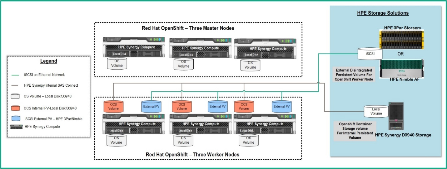
Figure 12. Logical storage layout within the solution
Table 16 lists all volume used within the solution and highlights what storage provides the capacity and performance of each function.
Table 16. Volume used in this solution
| Volume/Disk Function | Qty | Size | Source | Hosts | Shared/Dedicated |
|---|---|---|---|---|---|
| Local volume | 3 | 960GB | HPE Synergy D3940 storage | OpenShift worker nodes | dedicated |
| Operating System (optional) | 6 | 300GB | HPE Synergy D3940 storage | All nodes | dedicated |