# Physical Storage components
# HPE 3PAR Fibre Channel
# Initializing the HPE 3PAR StoreServ 8440 Storage
This section assumes that the HPE 3PAR StoreServ 8440 Storage was ordered with a physical service processor or with a Virtual Service Processor. VM is installed and functioning within the environment and is available on the same network as HPE Synergy Composer. It also assumes that a DHCP server is present on the network. The user should have the serial number of the storage that is being installed.
NOTE
Ensure that information such as user credentials, network access details and serial numbers referenced are securely recorded for current and future reference.
# Service Processor networking
To configure the Service Processor networking, use the following steps:
- Login to a physical Service Processor (SP) or access the console of a Virtual Service Processor via the virtual console.
- Log on as setupusr without a password.
- When you configure the network, type Y and press Enter.
- Confirm the network parameters that were handed to the Service Processor by your DHCP server and if correct, type Y and then press Enter. Ensure you note the IP address.
- When prompted, press Enter to exit. You will now configure the Service Processor. Connect to the SP using the address https://3par_ssmc_ip/sp/SpSetupWizard.html (opens new window), and log on with the user setupusr and no password.
- At the Welcome screen click Next.
- Enter the serial number of your HPE 3PAR StoreServ storage and select Generate SP ID. Click Next when done.
- On the Configure Service Processor Networking screen give the SP a hostname, check Enable DNS Support and enter the domain name and DNS server IP. Click Next.
- Enter any proxy information for Remote Support and click Next.
- Enter the appropriate information in the System Support Information screen and click Next.
- At the Time and Region screen, select Automatic and enter the IP address of your NTP server. Choose the appropriate Time Zone and click Next.
- When prompted, change the password and click Next.
- Click Next at the summary screen after validating all information.
- Remote connectivity will be tested. In the event of a failed test, ensure that the SP can speak outbound via HTTPS and that the proxy information entered is correct.
# Storage system
Use the following steps to configure the storage system.
From the SP, select Launch adjacent to the Storage System Setup Wizard and accept the EULA. Click Next.
Confirm the serial number of your array and click Next.
At the Configure Networking screen you will need to enter a name and network information for the array. Click Next.
Select Copy time options from the Service Processor and click Next.
Create a password for the 3paradm user and click Next.
Verify the configuration information and click Next. This will initialize and test the array and then add it to the SP. This process can take an extended amount of time. After all tests have passed, click Finish.
After completion, configure the Web services API and Common Information Module (CIM).
Log onto the array via SSH as the 3paradm user.
Run the following command to generate a self-signed certificate.
> createcert unified-server -selfsigned -keysize 2048 -days 1095 -CN <fqdn of 3PAR> -SAN "DNS:<fqdn of 3PAR>, IP:<management IP of 3PAR>"Answer Yes when prompted to continue creating the certificate.
Issue the following commands to start the WSAPI and CIM services.
> setcim -https enable
> startcim
> startwsapi
You can verify that the services are enabled and running by typing the following commands.
> showcim
> showwsapi
# SAN Switch configuration
The following steps should be repeated on each SAN switch:
Connect via the serial port to the first SAN switch and open a terminal session using 9600, 8, N and 1 with no flow control.
Logon as admin with the default password of ' password'. Change the passwords for admin and user as prompted.
At the command line, run the following commands to configure IP addressing for the switch.
> switchname <hostname of switch>
> ipaddrset
When prompted, turn off DHCP and configure date and time information for the switch.
> tstimezone ##
> date MMddhhmmyy
Here ## is the difference in the local time zone from GMT and MM is the 2-digit month, day is the 2-digit date, hh is the 2-digit hour (24-hour format), mm is the 2-digit minute and yy is the year.
- Configure the NTP Server with the following command.
> tsclockserver <ip address>
# Configure the fabric and licensing
The user will need to configure fabric and licensing in the environment.
Run the following command to configure the fabric name.
> fabricname --set <san_a_fabricname>Add any licenses by running the following command.
> licenseaddVerify all ports that will be used have been enabled. If you have not enabled, then run the following command.
> licenseport -reserveConfigure the Domain ID by typing the following.
> switchdisable
> configure
When prompted enter yes for Fabric parameters and assign a Domain ID. Once entered, press Control-D to exit.
> switchenableReboot the switch to apply changes and repeat these steps on the second switch.
# ISL Trunk the Fibre Channel switches
- Log in to each switch via SSH and use the licenseshow command to verify that the trunk license has been applied.
- On switch 1 and switch 2, run the portcfgpersistentdisable to disable the ports that will be used for ISL trunks.
- Run the portcfgislmode command and set the ports to mode 1 to make them ready for ISL traffic.
- Enable the ISL trunk ports on the switches by running the portcfgpersistentenable command.
- Run the trunkshow and fabricshow commands to verify that the trunk ports are configured and that both switches display the correct partner switch.
# Configure an active zone set
To allow HPE OneView for Synergy to manage the SAN fabric, the user must create an active zone set.
To create a zone using the WWPN of node 0, slot 0, port 1 on the HPE 3PAR StoreServ 8440, obtain the WWPN by typing switchshow and check the information on the switch port that 3PAR port N0:S0:P1 is connected.
Run the following commands to create the zone for this port.
> zonecreate <3PAR_1>_N0S0P1, "wwpn"
> cfgcreate solution_cfg, "<3PAR_1>_N0S0P1"
> cfgenable solution_cfg
3.Follow the prompts to enable the solution configuration.
4.Repeat these steps for the remaining SAN fabrics using the WWPN of each 3PAR node, slot, and port.
# Install and configure the HPE 3PAR SSMC
- From within the Windows management station, install the HPE 3PAR StoreServ Management Console by copying the media to the station and running the HPESSMC--win64.exe* user. Follow the onscreen prompts.
- Use a web browser to connect to https://3par_ssmc_ip:8443.
- Select Set credential and enter the username and password. Select Set.
- Install the HPE 3PAR Admin Tools by copying the media to the management server, mounting it and executing cli.exe. Follow the prompts to install. The user will need to add each array in the solution to the SSMC Administrator Console.
- Logon to the console and select Actions and then Add.
- Under System DNS names or IP addresses, enter the IP or name of the 3PAR array. The username will be 3paradm and the password is the one the user created earlier. Select Add.
- After the array appears in the NotConnected state, select it and select Actions and then AcceptCertificate. Select Accept and cache. After a moment, the array will appear in the Connected state.
- Repeat these steps for any additional arrays within the solution.
# Create Common Provisioning Groups (CPGs)
CPGs are required within this solution. By default, HPE 3PAR StoreServ arrays create a default set of CPGs.
Logon to the array as the 3PAR admin user using the SSMC.
Select 3PAR StoreServ -> Show all -> Common Provisioning Groups. Select Create CPG. Provide a descriptive name and use RAID6. The remaining default parameters are acceptable for this solution.
Create a second CPG for snapshots.
# Configure HPE OneView for Synergy to manage HPE 3PAR StoreServ resources
# Add a SAN Manager to HPE OneView for Synergy
- From the HPE OneView for Synergy interface, select OneView and then SAN manager.
- Select Add SAN manager and use the following values when prompted. Select Add when the values have been filled in.
- SAN manager type: Brocade Network Advisor
- IP address of hostname: <mgmt._vm_fqdn>
- Port: 5989
- User name: Administrator
- Password:
- Select OneView and then select SANs.
- Select the SAN switch hostname, hover over Zoning Policy and
select Edit. Click OK when done. For zoning parameters, use the
following values.
- Automate zoning: Yes
- Zone layout: Single initiator / single storage system
- Zone name format: server profiles _ server profile connection _ storage system _ storage system port group
- Check Update zone names as referenced resources are renamed
- Create aliases: Yes
- Manage pre-existing aliases: No
- Initiator alias format: Initiator _ server profile _ server profile connection
- Check Update initiator aliases as referenced resources are renamed.
- Target alias format: Target _ storage system _ storage system port
- Check Update target aliases and target group aliases as referenced resources are renamed.
- Create target group aliases: Yes
- Target group alias format: TargetGroup _ storage system _ storage system port group
- Repeat the steps for each SAN in OneView.
# Associate SAN networks with fabrics
- Select OneView and then Networks.
- Select SAN_A and then choose Actions -> Edit.
- In the Associated SAN field select the hostname of SAN switch 1 and click OK.
- Repeat these steps for SAN_B and associate it with the hostname of the second switch.
- Verify that the Expected Network is set to the correct SAN network for each port on the HPE 3PAR StoreServ storage. In the event of an error, check the wiring and previously entered settings and correct them.
- Enter the Port Group name and assign every pair of peer persistence ports to the same Port Group.
# Import and configure the HPE 3PAR StoreServ Storage
- Select OneView and then choose Storage Systems.
- Choose Add Storage Systems and enter the information for your array. Select Connect and ensure the storage shows up correctly.
- If needed, select a domain under the Storage domain dropdown.
- For Storage Pools, select the Manage checkbox for all of your previously created CPGs. Select Add.
# HPE 3PAR iSCSI
# Configure the management server
This section assumes that a physical or virtual management server running Microsoft Windows Server 2012 R2 is available and able to communicate on the same network as the HPE 3PAR StoreServ storage. If it is not, the user should create this management VM with the following: - Microsoft Windows Server 2012 R2 - 2 vCPU - 8GB RAM - 1x 100GB HDD for OS and applications - 1x 200GB HDD for Media - One (1) Network Interface connected to the management network where the storage resides
The management VM should have Microsoft IIS configured with the web server role and WebDAV publishing with basic authentication enabled. After the role is installed, perform the following steps.
In Server Manager select Tools and then Internet Information Services (IIS) Manager.
Select the server name and double-select MIME Types.
Select Add and enter the filename extension .vib as type application/octet stream.
Click OK.
Repeat this process but substitute the filename extension .iso for .vib.
Close the IIS Manager window.
Next the user will need to create a repository to house the Service Pack for ProLiant (SPP) and HPE Synergy Release Set hotfix update files associated with the HPE CA750 recipe.
From File Explorer navigate to the second HDD and create a folder named Media
Within the media folder, create a folder named SPP.
Copy the SPP and HPE Synergy release set files to this folder.
Create a folder under SPP and name the folder Hotfixes. Copy the SPP and/or HPE Synergy release set hotfix update files to this folder.
In Server Manager, relaunch Internet Information Services manager as in Step 1.
Expand the hostname and then expand Sites.
Right-click the default web site and select add virtual directory. Enter Media in the Alias field and select the media folder on the second drive for the physical path. Click OK twice when done.
From within IIS Manager ensure that the folders exist under default web site.
Select the Media folder and then double-select directory browsing and ensure it is Enabled.
Select default web site and double-click theWebDAV Authoring Rules icon. Select Enable WebDAV in the Actions Pane and then select Add Authoring Rule.
Select All content and All users radio button and then check the Read box under permissions. Click OK to commit.
WebDAV setting in the Actions pane and in the Property Behavior section, ensure that the Allow Anonymous Property Queries and Allow Property Queries of Infinite Depth are both set to True. Select Apply.
Select the Media directory in the left pane and in the right pane, double-click the HTTP Response Headers icon.
Select Add in the Actions pane and in the 'name' field enter MaxRepoSize. In the value field, enter the size of the drive that the Media folder was created on. In the case of this document you would enter 200G. Click OK when done.
Select the server name in the left pane and then in the Actions pane select Restart to restart the web server.
The next step is to create an external HPE OneView for Synergy repository. Follow the steps below:
a) Using Google Chrome, log on to the HPE Synergy Composer and navigate to OneView -> Settings
b) Select Repository and then select '+' to add repository.
c) Name the repo OneView Repo and in the web server address field enter http:///media/SPP
d) Uncheck the Requires Authentication checkbox and select Add.
# Install and configure the HPE 3PAR SSMC
- From within the Windows management station, install the HPE 3PAR StoreServ Management Console by copying the media to the station and running the HPESSMC-*-win64.exe installer. Follow the onscreen prompts.
- Use a web browser to connect to https://3par_ssmc_ip:8443.
- Select Set credential and enter the username and password. Select Set when done.
- Install the HPE 3PAR admin tools by copying the media to the management server, mounting it and executing cli.exe. Follow the prompts to install. The user will need to add each array in the solution to the SSMC Administrator Console.
- Log on to the console and select Actions and then Add.
- Under System DNS names or IP addresses enter the IP or name of the 3PAR array. The username will be 3paradm and the password is the one the user created earlier. Select Add.
- After the array appears in the Not Connected state, select it and select Actions and then Accept Certificate. Select Accept and cache. After a moment the array will show in the Connected state.
- Repeat these steps for any additional arrays within the solution.
# Create Common Provisioning Groups (CPGs)
CPGs are required within this solution. By default, HPE 3PAR StoreServ Storage Arrays create a default set of CPGs.
Log on to the array as the 3PAR admin user using the SSMC.
Select 3PAR StoreServ -> Show all -> Common Provisioning Groups.
Select Create CPG. Provide a descriptive name and use RAID6. The remaining default parameters are acceptable for this solution.
Create a second CPG for snapshots.
# Integrate HPE 3PAR StoreServ Storage to vSphere hosts
This section describes the process of creating hosts and storage volumes for the virtualization hosts. The steps below describes overview of the tasks.
Create hosts HPE 3PAR StoreServ Storage Management Console.
Create virtual volume for the vSphere hosts.
# Creating hosts
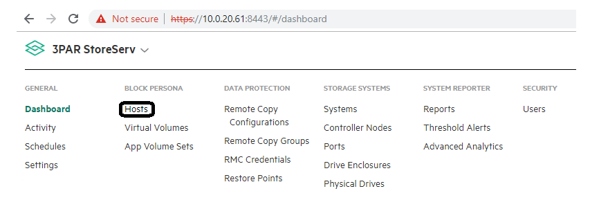
- Login to the 3PAR StoreServ Management Console. Select Hosts from the dropdown menu as shown.
On the Hosts page, click Create Hosts.
In the Create Host page, provide appropriate values for the variables.
- Name: <>
- System: <<3PAR storage system name>>
- Domain: None
- Host Set: NA
- Host OS: VMware (ESXi)
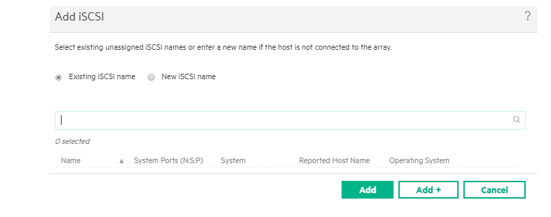
In the Paths section, click Add iSCSI. On the Add iSCSI page, provide the vSphere hostnames and IQN and then click Add. Repeat this step for all the vSphere hosts to permit all the vSphere hosts with access to the volume.
- After all values have been filled in, click Create.
# Creating virtual volume
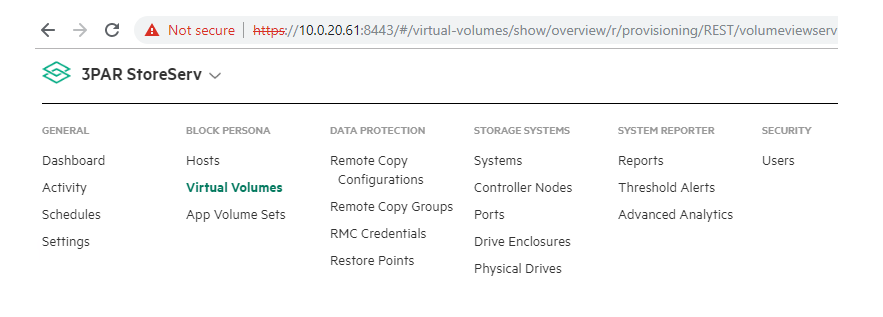
- Login to the 3PAR StoreServ Management Console. From the dropdown menu, navigate to Virtual Volumes as shown.
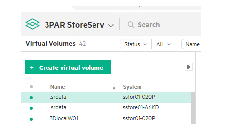
- Click Create virtual volumes.
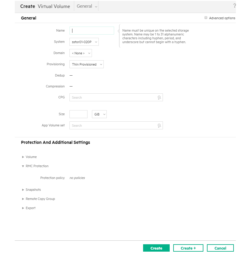
From the Create Virtual Volume page, provide values for the following fields and click Create.
- Name:
- System: <3PAR storage system name>
- Domain: None
- Provisioning: Thin Provisioned
- Dedup: No
- Compression: No
- CPG:
- Size: 3TB
- Volume Set: NA
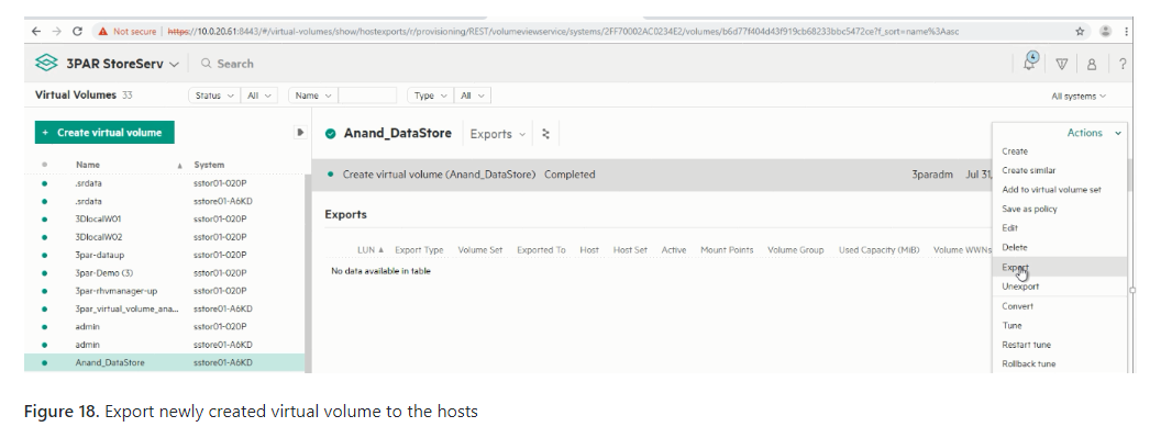
- After the Virtual volume has been created, select the Export option in the Actions drop down menu.
- From the Export Virtual Volumes page, click Add.
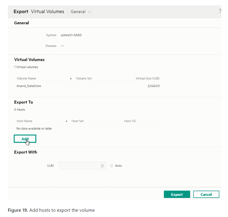
From the Add page, select the host to which the virtual volume needs to be exported and click Add.
After adding the host, select the LUN Auto check box and then click Export.
# HPE Nimble iSCSI
# Integrate HPE Nimble Storage with vSphere hosts
- Create initiator groups in the HPE Nimble Storage management console.
- Create a volume for the ESXi hosts.
# Create initiator groups in the HPE Nimble Storage management console
The initiator group allows connecting volumes directly to the IQNs of the iSCSI adapters. From the HPE Nimble Storage management console, initiator groups should be created with the IQNs of each of the ESXi hosts. Initiator groups can be created by following the steps outlined as follows:
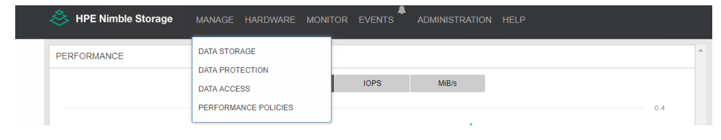
Log in to the HPE Nimble Storage management console.
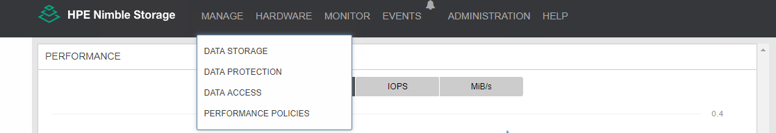
Navigate to Manage -> Data Access.
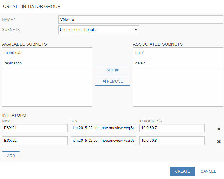
- On the Create Initiator Group page, enter the details for the
following parameters.
- Name: < Name of the initiator group >
- Subnets: From the drop-down menu, select Use selected subnets and add the selected data subnets.
- Initiators: Add the name and IQNs of all the initiators (vSphere hosts), and click Create.
NOTE
IQNs can be found in the Server Profile of the ESXi hosts in HPE OneView. If hosts are already added into the cluster of vCenter, IQNs can be found at Host > Configuration > Storage Adapter > Highlight your iSCSI Software Adapter > Details.
# Create a volume for the ESXi hosts in HPE Nimble Storage management console
After the initiator group is created, perform the following to provision a new volume to store the management virtual machines. A minimum volume size of 3TB is recommended to host the management nodes.
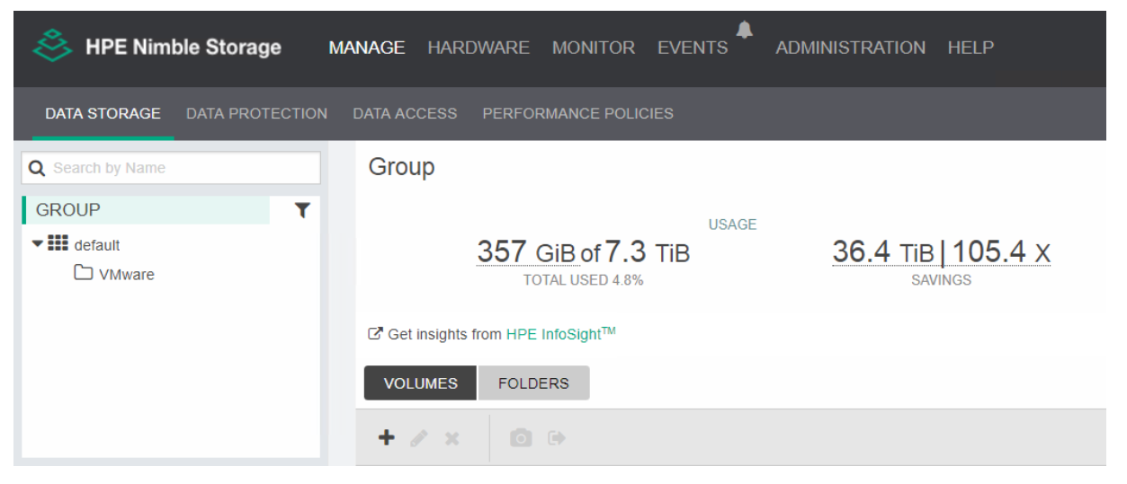
- From the HPE Nimble Storage management console, navigate to MANAGE -> DATA STORAGE.
- Click "+" icon to create a new volume.
- Provide the values to the following parameters for creating a
volume. Sample values for the parameters are listed as follows.
- Name: < Name for the Volume >
- Location: < Desired location of the Volume >
- Performance policy: < Assign a performance policy for the volume>
- Size: As per the need of user environment ( 3TB recommended).
- Protection policy: Assign a protection policy as required.
- Access: Assign the initiator group for the vSphere hosts created earlier.
- CHAP Account: Assign the CHAP account and select the Allow Multiple Initiator access box.
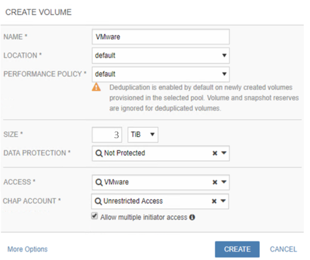
- Click Create to complete the volume creation.
NOTE
If you utilize virtual worker nodes, it is recommended to create another volume with a size based on the installation environment. 1TB is the minimum recommended size.