# Physical Environment components
This section outlines the steps to be performed to configure the physical environment used in this solution
# Rack wiring between the Servers and the network switches
This section shows the physical cabling between frames, Virtual Connect modules and solution switching. It is intended to provide an understanding of how the infrastructure was interconnected during testing and to serve as a guide on which the installation user can base their configuration.
Figure 5 describes the cabling configuration of the three (3) HPE ProLiant DL360 and HPE ProLiant DL380 Gen10 servers as well as the HPE FlexFabric 5945 Switches and Intelligent Resilient Fabric (IRF) within the context of this solution. These cables carry frame management, inter-frame and interconnect traffic between frames.
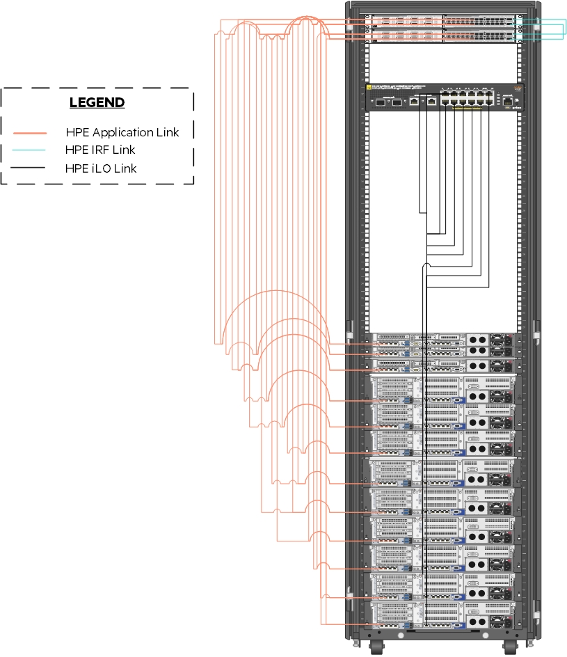
Figure 5. Rack wiring between the Servers and the network switches
# Cabling of the HPE Nimble Storage and HPE 3PAR for iSCSI
An HPE Nimble Storage AF40 array provides shared and dedicated storage for a variety of purposes within this solution. Figure 6 shows the cabling of the HPE Nimble Storage AF40 to the HPE switching utilized in this solution. Note that this diagram shows the storage and switching in the same rack to provide clarity. As implemented for this solution, the switching resided in the rack. The orange and purple wires in the figure represent the separate iSCSI VLANs.
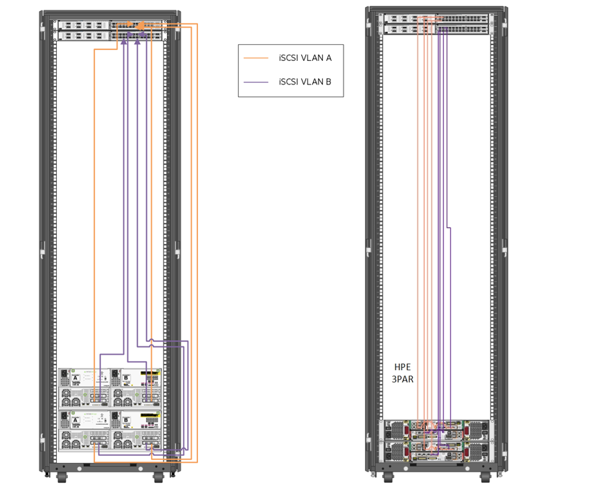
Figure 6. Cabling of the HPE Nimble Storage arrays Or HPE 3par Storage arrays to the HPE FF 5940 switches
# Cabling of the HPE 3PAR StoreServ
HPE 3PAR StoreServ 8440 Storage provides shared and dedicated storage within this solution. Figure 7 shows the iSCSI cabling of the HPE 3par storage array to the TOR switch. Cabling for each array follows the same guidelines for maximum availability.
For Fiber Channel connectivity HPE 3PAR StoreServ 8440 Storage provides shared and dedicated storage within this solution. Figure 7 shows the cabling of the HPE ProLiant DL 380 and DL 360 servers to the HPE Fiber Channel switching and cabling of the HPE 3PAR StoreServ 8440 Storage to the HPE Fiber Channel switching utilized in this solution. Cabling for each array follows the same guidelines for maximum availability.
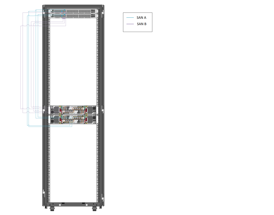
Figure 7. Cabling of the HPE ProLiant DL380 and DL360 interconnects and HPE SN6600B switching