# Physical environment configuration
This section outlines the steps to be performed to configure the physical environment used in this solution
# Cabling the HPE Synergy 12000 Frame
Cabling the HPE Synergy 12000 Frame and HPE Virtual Connect 100Gb SE F8 Modules for HPE Synergy
This section shows the physical cabling between frames, Virtual Connect modules, and solution switching. It is intended to provide an understanding of how the infrastructure was interconnected during the testing and to serve as a guide on which the installation user can base their configuration.
Figure 7 describes the cabling configuration of the three (3) HPE
Synergy 12000 Frames as well as the HPE Aruba 8325-32C BF switches and
Aruba VSX, that takes advantage of the ArubaOS-CX modern architecture,
and delivers best in class high availability within the context of this
solution. These cables carry frame management, inter-frame, and
interconnect traffic between frames.
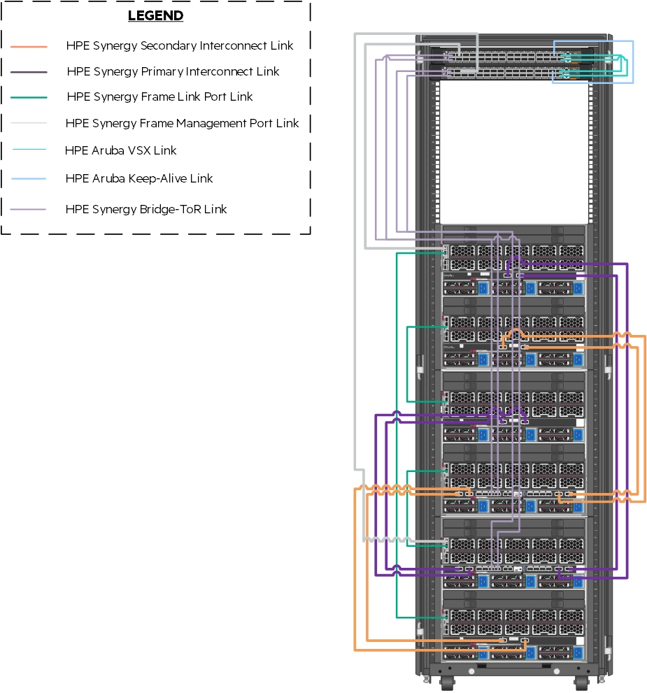
Figure 7. Cabling of the management and inter-frame communication links within the solution
Figure 8 shows describes the cabling of the solution from the HPE
Virtual Connect SE 100 GB modules to the switches and the network
carried on each connection. In the HPE Synergy environment, this first
layer of switching is at the end of the row rather than the top of the
rack switching. Top of the rack was used for solution development.
Switching is flexible based on the installation environment and top of
the rack switching may be substituted with the end of the row switching.
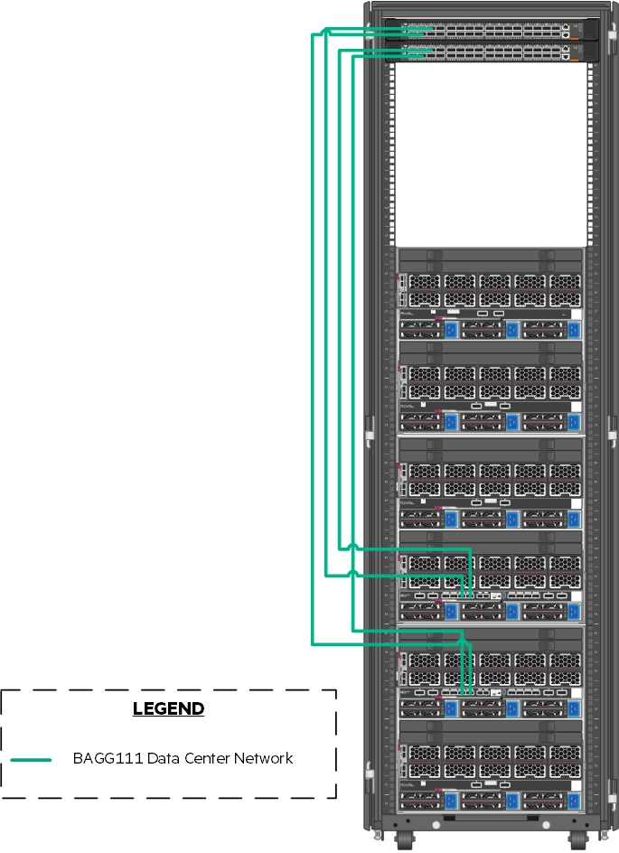
Figure 8. Network cabling from the HPE Synergy 12000 Frame to the switches
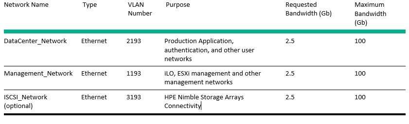
Table 5 explains the cabling of the Virtual Connect interconnect modules to the HPE Aruba 8325-32C switching.
# Table 5 Network used in this solution
# Configuring the solution switching
The solution described in this document utilized HPE Aruba 8325-32C switches. The HPE Aruba 8325-32C switches are configured according to the configuration parameters found later in this section. Individual port configuration is also described in this section. The switches should be configured with an HPE Intelligent Resilient Framework (IRF). To understand the process of configuring IRF, refer to the HPE Aruba 8325-32C Switch Series Installation Guide at https://support.hpe.com/hpesc/public/docDisplay?docId=a00065374en_us&docLocale=en_US (opens new window). This guide may also be used to understand the initial installation of switching, creation of user accounts, and access methods. The remainder of this section is built with the assumption that the switch has been installed, configured for IRF, hardened, and is accessible over SSH.
NOTE
The installation user might choose to utilize end of row switching to reduce switch and port counts in the context of the solution. If you follow end of row switching as the approach, then this section should be used as a guidance on how to route network traffic outside of the HPE Synergy Frames.
# Physical cabling
Table 6 represents mapping of source ports to ports on the HPE Aruba 8325-32C switches.
Table 6. HPE Aruba port map

Hewlett Packard Enterprise recommends that the installation user logs on to the switch, post-configuration and provide a description for each of these ports.
# Network definition
There are multiple networks defined at the switch layer in this solution:
Management Network -- This network facilitates the management of hardware and software interfaced by IT.
Data Center Network -- This network carries traffic from the overlay network used by the pods to external consumers of pod deployed services.
Table 5 defines the VLANs configured using HPE Synergy Composer in the creation of this solution. This network should be defined at both the first layer switch and within the composer. This solution utilizes unique VLANs for the data center and solution management segments. Actual VLANs and network count will be determined by the requirements of your production environment.
# Configure VLAN
This section details the steps required to configure a VLAN.
- To add these networks to the switch, logon to the switch console over SSH and run the following commands.
> sys
> vlan 1193 2193
- For each of these VLANs, perform the following steps.
> interface vlan-interface ####
> name VLAN Name per table above
> description Add text that describes the purpose of the VLAN
> quit
NOTE
Hewlett Packard Enterprise strongly recommends configuring a dummy VLAN on the switches and assign unused ports to that VLAN.
- The switches should be configured with a bridge aggregation group (BAGG) for the different links to the HPE Synergy Frame connections. To configure the BAGG and ports as described in Table 5, run the following commands.
> interface Bridge-Aggregation111
> link-aggregation mode dynamic
> description <FrameNameU30>-ICM
> quit

> interface range name <FrameNameU30>-ICM interface
Bridge-Aggregation111
> quit

> interface range HundredGigE 1/1/1 to HundredGigE 1/1/2 HundredGigE
2/1/1 to HundredGigE 2/1/2
> port link-aggregation group 111
> quit

> interface range name <FrameNameU30>-ICM
> port link-type trunk
> undo port trunk permit vlan 1
> port trunk permit vlan 1193 2193
> quit
- After the configuration of the switches is complete, save the state and apply it by typing save and follow the resulting prompts.
# HPE Synergy 480 Gen10 Compute Modules
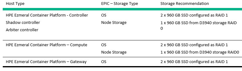
This section describes the connectivity of the HPE Synergy 480 Gen10 Compute Modules used in the creation of this solution. The HPE Synergy 480 Gen10 Compute Modules, regardless of function, were all configured identically. Table 7 describes the host configuration tested for this solution. Server configuration should be based on customer needs, and the configuration used in the creation of this solution might not align with the requirements of any given production implementation.
Table 7. Host configuration
# HPE Synergy Composer 2
At the core of the management of the HPE Synergy environment is HPE Synergy Composer 2. A pair of HPE Synergy Composers are deployed across frames to provide redundant management of the environment for both initial deployment and changes over the lifecycle of the solution. HPE Synergy Composer 2 is used to configure the environment prior to the deployment of the operating systems and applications.
This section guides the installation user through the process of installing and configuring the HPE Synergy Composer.
# Configure the HPE Synergy Composer via VNC
To configure HPE Synergy Composer with the user laptop, follow these steps:
Configure the laptop Ethernet port to the IP address 192.168.10.2/24*.* No gateway is required.
Use a CAT5e cable to connect the computer Ethernet port to laptop port on the front panel module of HPE Synergy Composer.
Use a web browser to access the HPE Synergy console. Start a new browser session and enter http://192.168.10.1:5800 (opens new window).
Click Connect to start HPE OneView for Synergy from the HPE Synergy console.
Click Hardware Setup to connect with Installation Technician user privileges.
In the Appliance Network dialog box, fill in the following information
a. Appliance host name: Enter a fully qualified name of the HPE Synergy Composer.
b. Address assignment: Manual
c. IP address: Enter an IP address on the management network.
d. Subnet mask or CIDR: Enter the subnet mask of the management network.
e. Gateway address: Enter the gateway for the management network.
f. Maintenance IP address 1: Enter a primary maintenance IP address on the management network.
g. Maintenance IP address 2: Enter a secondary maintenance IP address on the management network.
h. Preferred DNS server: Enter the DNS server.
i. IPv6 Address assignment: Unassign
Click OK.
When the hardware discovery process is complete, all HPE Synergy hardware including the Frames, Composer modules, Frame Link modules, Interconnect modules, Compute modules, and storage modules must be discovered and claimed by HPE OneView for Synergy.
Review and correct any issues listed in the hardware setup checklist. The HPE Synergy 12000 Frame Setup and Installation Guide is available at https://psnow.ext.hpe.com/doc/c05348240 (opens new window) provides resolution for troubleshooting steps of common issues during hardware setup.
Navigate to OneView -> Settings and then click Appliance. Verify that the active and standby appliances show a status of Connected.
# Configure appliance credentials
Login to HPE OneView for Synergy Web Administration portal. Review and accept the License Agreement.
On the HPE OneView Support Dialog box, verify that Authorized Service has a setting of Enabled. Click OK.
Login as Administrator with default password admin. Set the new password to <<composer_administrator_password>> and click Ok.
# Configure solution firmware
HPE Synergy Firmware is regulated according to a given HPE Synergy software release, which includes the software version of HPE OneView for Synergy on HPE Synergy Composer and the HPE Synergy Custom SPP firmware bundle for all other HPE Synergy components. At this stage, update the HPE Synergy Composer. The guided setup takes care of the firmware updates to the remaining HPE Synergy components.
# Solution configuration
The installation user should utilize the Synergy guided setup to complete the following solution configuration details. Perform all the steps of guided setup that are relevant to the environment. Skip steps that are irrelevant to your setup.
On the upper right-hand corner, click Guided setup -> First step, to begin the Guided setup.
Select the appropriate check boxes based on your solution under the Customize OneView Experience heading.
Click << to see the list of recommended appliance configuration steps based on the previous selection.
Proceed through the Guided setup process following the recommendations outlined in the subsequent sections. Place a check mark in the complete box for each step that is successfully completed.
# Create additional users
Hewlett Packard Enterprise recommends that you create a read-only user and an administrator account with a different username other than administrator.
# Create an IP pool on the management network
Follow the guided setup to create an IP pool on the management network. This IP pool will provide IP addresses to management IPs, and HPE device iLOs within the solution. Ensure that the pool is enabled before proceeding.
# Configure Ethernet networks
As explained in the Network definition section of this document, the solution utilizes four (4) network segments. Refer to the Create network section of the OneView Guided Setup wizard to define the network as shown in Table 8. Your VLAN values will generally differ. Table 8 describes the network defined within HPE Synergy Composer for this solution.
Table 8. Network defined within HPE Synergy Composer for this solution
 The management network should be associated with the management network
IP pool that is specified by the user. The installation user should
create any additional required network for the solution.
The management network should be associated with the management network
IP pool that is specified by the user. The installation user should
create any additional required network for the solution.
# Create Logical Interconnect Groups
Within Composer, use the Guided Setup to create a Logical Interconnect Group (LIG) with three (3) uplink sets defined. For this solution, the uplink sets are named Network, iSCSI_SAN_A, and iSCSI_SAN_B. The uplink sets "Network" carries all other network defined for the solution. The iSCSI uplink sets carry the respective iSCSI VLANs. Table 5 defines the ports used to carry the uplink sets.
# Create Enclosure Group
From the OneView Guided Setup, select Create enclosure group.
Provide a name and enter the number of frames.
Select Use address pool and utilize the management pool defined earlier.
Use the Logical Interconnect Group from the previous section in the creation of the Enclosure Group.
Select Create when ready.
# Create Logical Enclosure
Use the Guided Setup to create a logical enclosure to make use of all three (3) enclosures. Select the firmware you uploaded earlier as a baseline. It can take some time for the firmware to update across the solution stack. Select Actions and then Update Firmware to ensure that the firmware complies with the baseline. Click Cancel to exit.